
Theory · D+E Licence - Bus with Trailer · Module 4 of 13
Safe coupling and uncoupling
You learn to couple and uncouple your bus trailer while keeping both units immobilised, the coupling locked and the connections in working order. You master the sequence of supports, safety locks, service connections and checks so that you can identify in the D+E exam which action prevents unexpected movement or accidental separation.
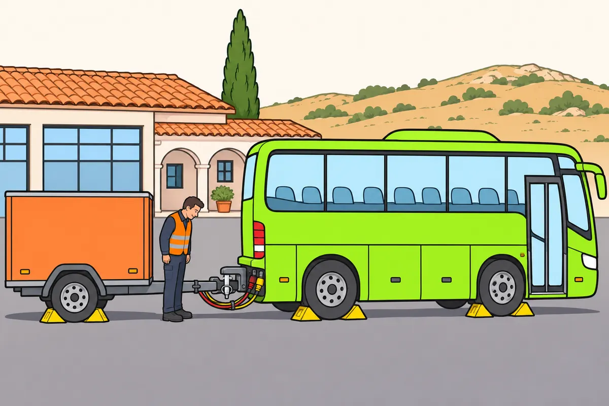
1What you must secure when coupling
Secure the coupling, its safety lock and the services fitted to your combination.
Remember
- Identify the coupling and its controls before approaching.
- Secure the mechanical connection and its safety lock.
- Connect the services fitted to your combination.
- Follow the procedure for your bus, trailer and coupling.
Exam trap: Wrong: use the same steps for every system. Right: follow the procedure for your combination and its fitted brakes, supports and indicators.
Read the full explanation
- When coupling the luggage trailer, secure the mechanical connection, engage its safety lock and connect the services fitted to the combination. Identify the coupling and its controls before moving the bus towards it.
- Follow the procedure specified by the bus, trailer and coupling manufacturers for the brakes, supports and indicators fitted. Lever positions and locking indications depend on the model; locate the instructions and check that you can recognise them from the intended working position.
2Compatibility before approaching
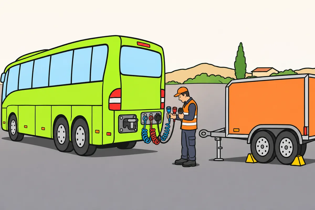
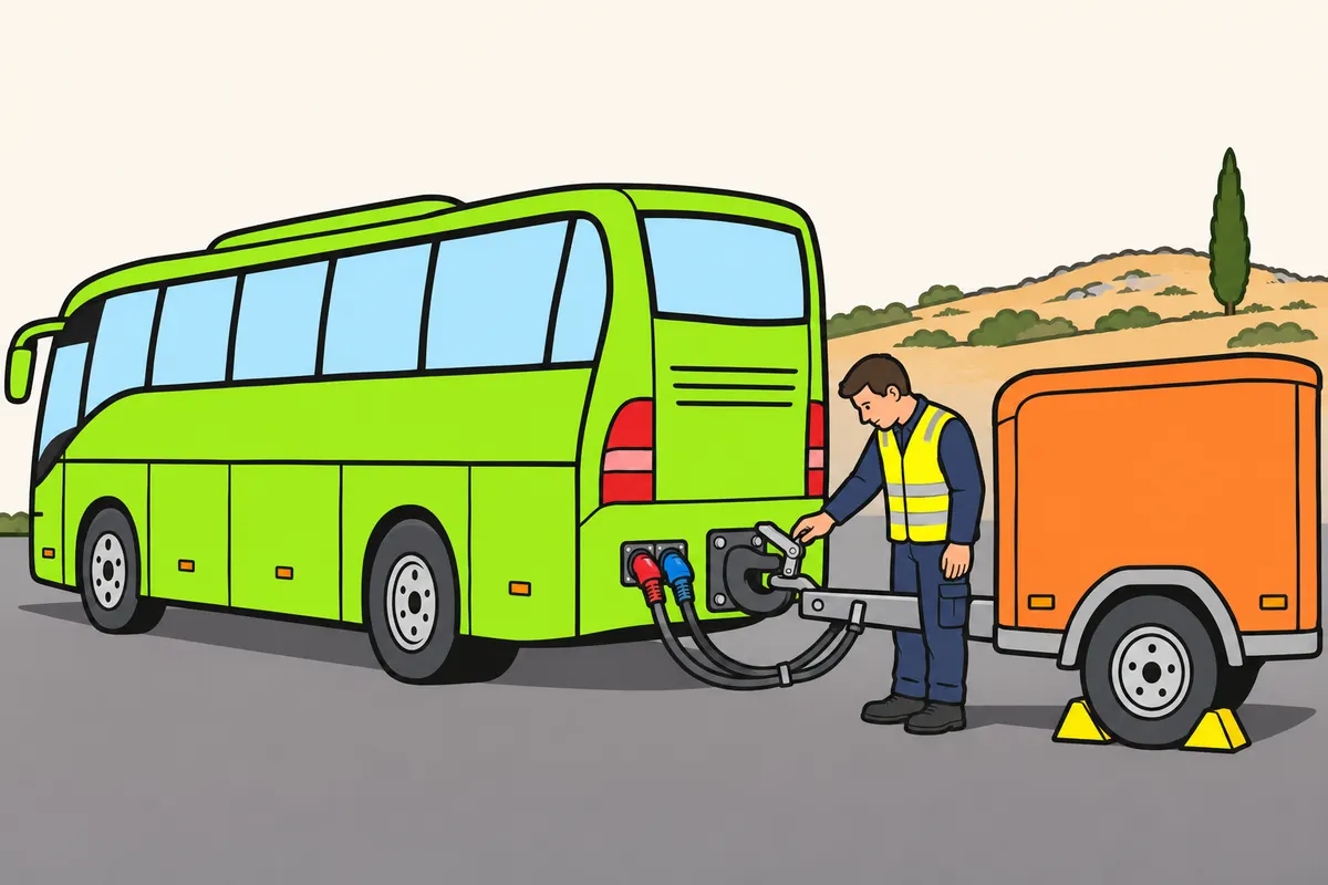
Check that the bus, trailer and all their connections are technically compatible.
Remember
- Check mechanical, air and electrical connections.
- Check the technical specifications allow your bus and trailer to work together.
- Never force a connection or improvise an adapter.
- Identify your trailer’s brakes, supports and controls.
- Keep passengers outside the coupling area.
Exam trap: Wrong: assume a part is suitable because it fits. Right: check that all components are technically compatible.
Read the full explanation
- Use compatible mechanical, pneumatic and electrical connections between the bus and the trailer. A connector fitting under pressure or a drawbar coming close to the coupling does not establish compatibility; do not force connections or improvise adaptations. This requirement applies to all three types of connecting components. [RGV, art. 13.1](https://www.boe.es/buscar/act.php?id=BOE-A-1999-1826#a13).
- Confirm that the technical specifications of the components permit the combination. A coupling that physically allows connection may be unsuitable for that trailer or for the forces it must withstand. Mass calculations are covered in the module «Dimensions, masses and speed limiters».
- Identify the connections and supports actually fitted to your luggage trailer. A combination with an overrun brake may require different preparation from one with pneumatic and electronic braking. Also check where the controls and anchor points are, without allowing passengers approaching to collect their bags to enter the coupling area.
3Site and working area
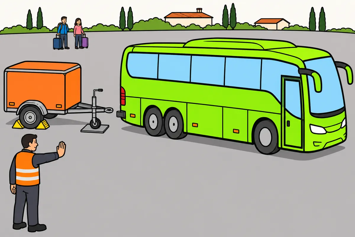
Choose stable ground and keep people clear of the manoeuvring area.
Remember
- Choose firm, stable ground, as level as possible.
- Check that the ground will support the detached trailer’s supports.
- Check obstacles and spaces outside the view of cameras and mirrors.
- Keep people clear of the vehicle path and the space between vehicles.
- Agree clear signals and a safe position with anyone guiding you.
- Stop if you lose sight of your guide or someone enters the area.
Exam trap: Wrong: keep approaching when you cannot see your guide. Right: stop until you can see them and the area is safe.
Read the full explanation
- Choose a firm, stable surface that is as level as possible. Pay particular attention to where the jockey wheel or drawbar supports will rest: ground that supports the tyres may give way under a small support. Plan for the stability of the detached trailer before releasing the coupling. [SAF-HOLLAND, support devices, section 6.5](https://literature1.safholland.com/sites/damedit/literature/FH-LG_Hercules_dropleg_es-DE.pdf).
- Allow enough space to align the bus, approach slowly and move it away without hitting the trailer. Check for overhead, side and low-level obstacles, and the path of the rear of the bus during the manoeuvre. The camera or mirrors can help, but also check the space outside their field of view.
- Keep people out of the space between the vehicles while either vehicle can move. If someone helps you, agree on clear signals and a visible, safe position for the person guiding you. Stop when you lose sight of that person; never use their proximity to the coupling as a reference for continuing to approach. During a passenger service, also keep people waiting and those handling luggage out of the path of the bus and drawbar.
4Immobilise before getting out
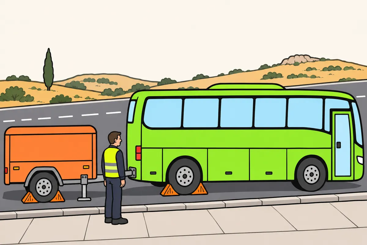
Secure both units against movement before you work on foot.
| Combination parked on a slope | Gearbox position | Wheel direction if using a kerb |
|---|---|---|
| Uphill | First gear or the appropriate parking position | Towards the centre of the carriageway |
| Downhill | Reverse gear or the appropriate parking position | Away from the carriageway |
Remember
- Switch off the engine and ignition and apply the parking brake before getting out.
- If you move away, prevent unauthorised use of the vehicle.
- Apply the trailer parking brake and any extra means required.
- On significant slopes, add suitable chocks or rest a steered wheel against suitable kerbing.
- Do not use stones as chocks.
- With the described two-button valve, pull red to park; black releases brakes for manoeuvring.
Exam trap: Wrong: use the black button to park. Right: if the described valve is fitted, pull the red button; the black button releases brakes for manoeuvring.
Read the full explanation
- Before working on foot at the coupling, immobilise both units using their parking brakes and the additional means specified. If the trailer has the two-button valve described, pull the red button to apply its parking brake. The black button allows you to release the automatic braking to manoeuvre using stored air: it serves a different purpose. [Fliegl, manual, sections 6.4.3-6.4.4](https://fliegl-agrartechnik.de/fileadmin/datenblaetter_user/EN/Product%20line%20%E2%80%93%20Push-off%20technology/Trailers/Previous%20series/ASW%20push-off%20trailer/Operating%20instructions%20ASW%20push-off%20trailer_EN_3.0.pdf).
- When leaving the driving position after halting or parking, switch off the engine, switch off the ignition and apply the parking brake; if you move away, prevent unauthorised use. If the vehicle has a gearbox, leave it in first gear facing uphill, reverse facing downhill or the appropriate parking position. [RGC, art. 92.3.a-c](https://www.boe.es/buscar/act.php?id=BOE-A-2003-23514#a92).
- On a significant gradient, also secure your combination with suitable wheel chocks or rest a steered wheel against a suitable kerb. For the latter option, turn the wheels towards the centre of the carriageway when facing uphill and away from it when facing downhill. Do not use stones or improvised objects. [RGC, art. 92.3.d](https://www.boe.es/buscar/act.php?id=BOE-A-2003-23514#a92).
5Inspect the coupling components
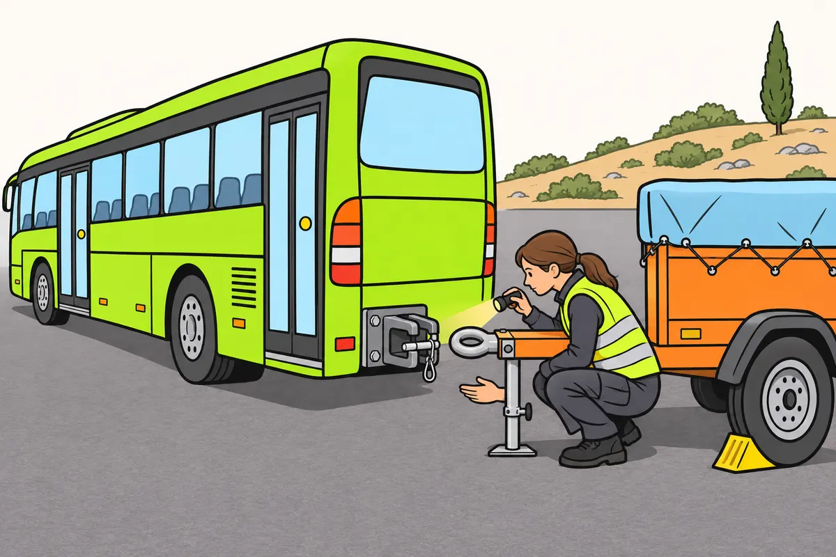
Check the coupling parts for damage, dirt, wear and correct lubrication.
Remember
- Look for cracks, bends, wear and missing parts.
- Check fixings, latches and surfaces that join.
- On drawbar couplings, check the towing eye, pin or hook and safety lock.
- Remove dirt that prevents parts seating or locking.
- Follow the device’s own lubrication instructions.
- Stop and request an inspection if a part is deformed.
Exam trap: Wrong: grease every surface of the coupling head. Right: follow the specific lubrication instructions.
Read the full explanation
- Inspect the fixings, latches and contact surfaces before joining them. Look for missing parts, deformation, cracks, abnormal play and dirt that prevents seating or locking. Do not try to overcome a deformed component by hitting it harder with the bus; stop the operation and request an appropriate inspection.
- With a drawbar coupling, the towing eye must seat in the working area of the pin or hook without interference that hinders its retention. Consult the wear limits and permitted dimensions for the paired components; a similar appearance does not guarantee that they can work together. [SAF-HOLLAND, PH-410 operation and maintenance](https://docs.safhollandmexico.com/productos/manuales/XL-PH342_es-US.pdf).
- Maintain the surfaces in accordance with the device's specific lubrication instructions. You cannot decide when to grease it based on a generic interval or apply grease to every surface of the coupling head. Dirt and incorrect lubrication can impair locking or friction; detailed maintenance is covered in the module «Maintenance and inspection of the vehicle combination».
6Align the bus and trailer
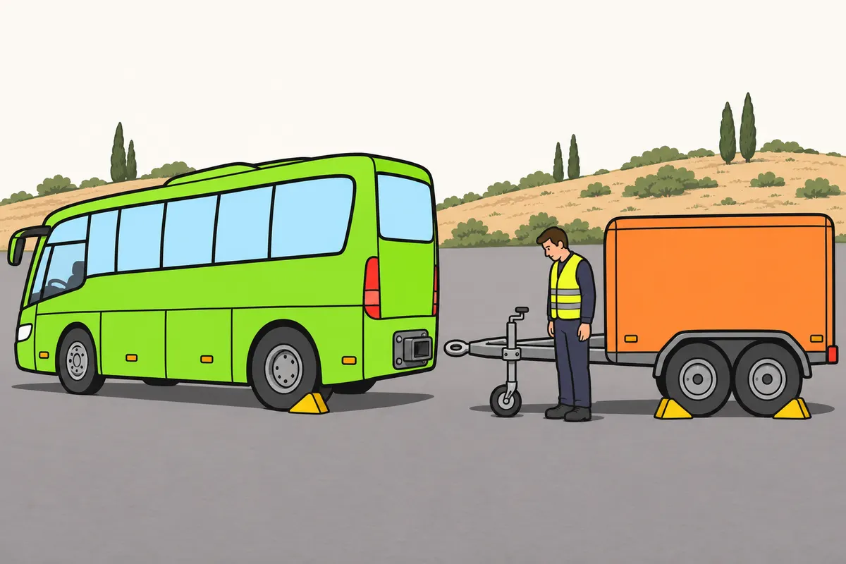
Align the coupling and drawbar, then approach slowly with a clear view.
Remember
- Point the coupling towards the drawbar.
- Adjust height using the designated support, keeping the trailer braked and stable.
- Check that the parts line up before contact.
- Allow for the rear of the bus to swing.
- Reverse very slowly; stop for resistance, misalignment or uncertain visibility.
- Stop and check on foot if you cannot judge the actual position.
Exam trap: Wrong: use a fixed height for every coupling. Right: adjust the height to suit your equipment and check alignment.
Read the full explanation
- Approach with the bus coupling pointing towards the drawbar, using mirror or camera reference points that let you locate both components. Stop moving and check on foot when those reference points do not let you judge the actual position of the towing eye relative to the coupling mouth.
- Adjust the drawbar height using the jockey wheel or designated support, keeping the trailer braked and stable. The correct height depends on the coupling and equipment; there is no clearance in centimetres that you can apply to every bus. Check alignment before the components meet and prevent contact from causing the support to collapse.
- Allow for the bus's rear overhang when correcting the steering. Movement of the rear can bring the bodywork close to the drawbar or to people beside the trailer. Make small corrections and stop to reassess the approach if you lose the correct angle or safe clearance.
- Reverse very slowly and stop if you encounter abnormal resistance, lose alignment or have doubts about visibility. The coupling mouth guides entry within the range specified by the manufacturer; an impact against its edge can damage the device or displace the support. Make corrections using the equipment's adjustment mechanisms.
7Close and lock the coupling
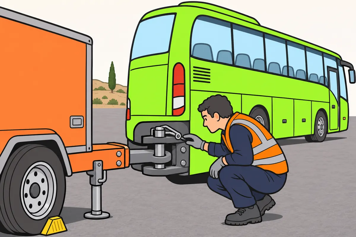
Check that the coupling has captured the drawbar and its safety lock works.
Remember
- Complete coupling for your system; check that the retaining part is in position.
- Check that the safety lock prevents accidental separation.
- Never replace a missing safety lock with an improvised tie.
- Read the indicators according to the manual.
- Investigate visible faults even if the indicator shows correct locking.
Exam trap: Wrong: assume the coupling is secure after hearing a knock. Right: check the latch and its safety lock.
Read the full explanation
- Complete the coupling procedure for the system fitted and check that the retaining component is in its working position. A closing sound or the drawbar simply resting on the coupling does not prove that the connection is secure.
- Check the component that prevents unintended uncoupling: the coupling device must incorporate one. You must not replace a missing safety lock with an improvised tie or disable it to make the work easier. [RGV, art. 13.3](https://www.boe.es/buscar/act.php?id=BOE-A-1999-1826#a13).
- Interpret the electronic or mechanical indicators according to the manual and carry out the checks required for that system. If the cab warning contradicts the visible state of the mechanism, the coupling needs inspection. The indicator lets you identify whether the coupling is locked, but each manufacturer specifies the direct visual check that must accompany it.
8Check mechanical retention
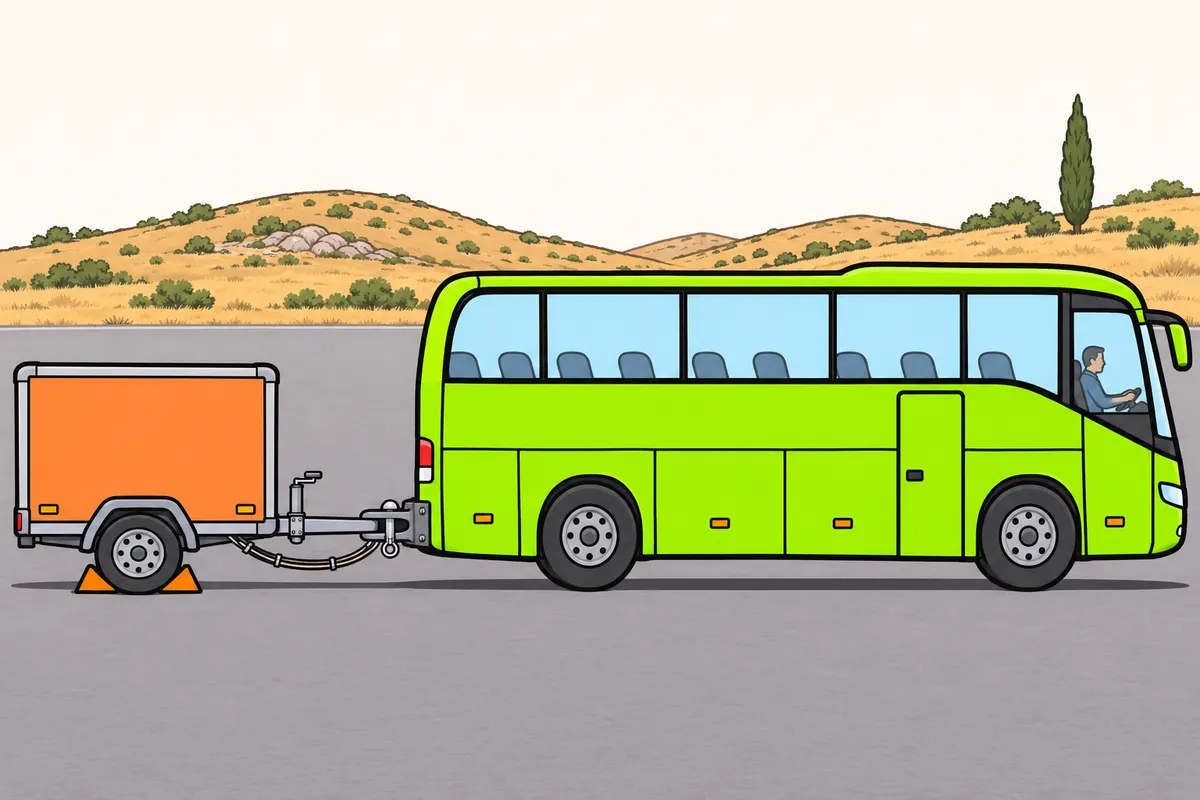
Use the retention check and force specified by the coupling maker.
Remember
- Use a gentle pull only if the manual requires it.
- Keep the trailer restrained and supports in the stated position.
- Observe the coupling from the position specified for your equipment.
- Stop if anything moves unexpectedly.
- If the check fails, immobilise and keep the trailer supported while checking.
- Request assistance for faults, wear or if you cannot confirm retention.
Exam trap: Wrong: accelerate hard to test the coupling. Right: use the gentle force specified in the manual.
Read the full explanation
- Carry out the retention check specified by your coupling manufacturer. If it includes a gentle pull, keep the trailer restrained and the supports in the position specified for that test. Apply enough force to check the connection without moving the trailer or subjecting the mechanism to a violent jerk; use the specific procedure for the drawbar and towing eye.
- Select the control and apply the force specified in the manual, and stop if any unexpected movement occurs. Observe the coupling from the position the equipment allows, with assistance if specified. Hard acceleration can cause damage and does not provide a more reliable check than the gentle manoeuvre specified.
- If the check fails, keep the trailer supported while you check alignment, height and locking according to the manual. Do not move off until you resolve the incorrect engagement. If there is wear or a fault, or you cannot confirm retention, request technical assistance and explain which indicator or component prevents you from completing the check.
9Drawbar and towing-eye coupling
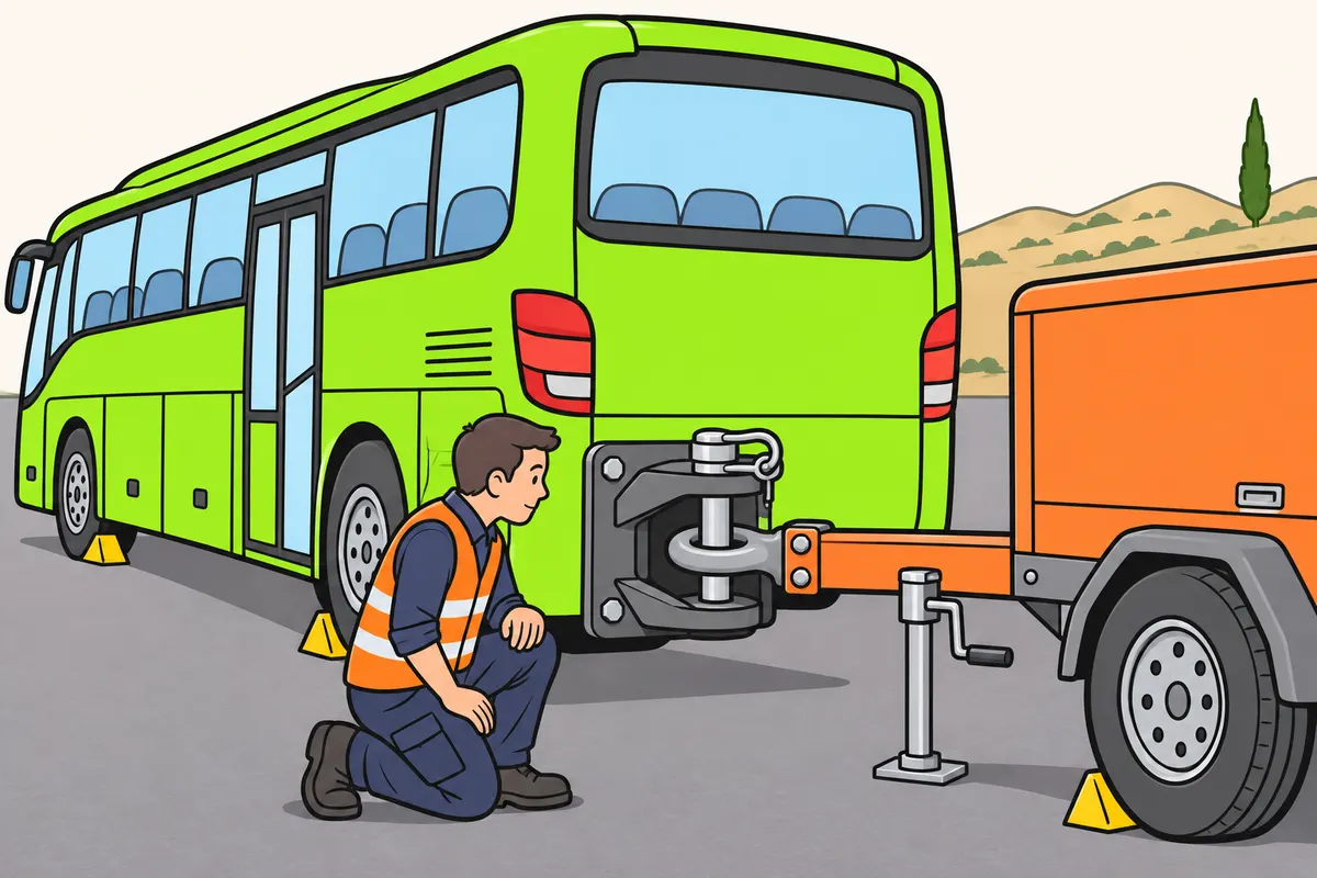
Align the towing eye and check that the pin fully holds and locks it.
| Drawbar coupling type | What you check |
|---|---|
| Automatic | Full locking cycle and control in the stated position |
| Manual | Specified closing and locking steps completed |
Remember
- Adjust the drawbar height using the system provided.
- Do not support a heavy drawbar with your body.
- Approach slowly with the bus; stop if the parts do not line up.
- Check that the pin is fully in position and secured.
- With automatic coupling, check locking and the control’s final position.
- With manual coupling, complete the specified closing and locking steps.
Exam trap: Wrong: assume the towing eye is safe inside the coupling mouth. Right: check that the pin holds it and is secured.
Read the full explanation
- On a trailer with a towing eye, adjust the drawbar using the system provided until it lines up with the centre of the coupling mouth. A heavy drawbar requires its supporting device; avoid lifting it by improvised means or supporting it with your body. To guide it manually, use the designated handhold, away from the path of the coupling pin.
- Prepare the automatic or manual coupling according to its design and bring the bus closer slowly. Do not use the edge of the bodywork to push or straighten the drawbar. If it does not line up with the opening, stop the vehicle and correct the position using suitable means before continuing to couple.
- Once the towing eye has entered, check that the pin is fully in its working position and securely retained. Observe the relevant locking indicator and check the accessible components according to the manual. A towing eye inside the coupling mouth is still unsafe if the pin does not retain it.
- With an automatic coupling, check that entry of the towing eye has completed the locking cycle and that the control has returned to the position specified by the manufacturer. With a manual coupling, complete the closing and locking operations specified for that mechanism. Automatic locking does not replace the need to check it.
10Ball coupling head, if fitted
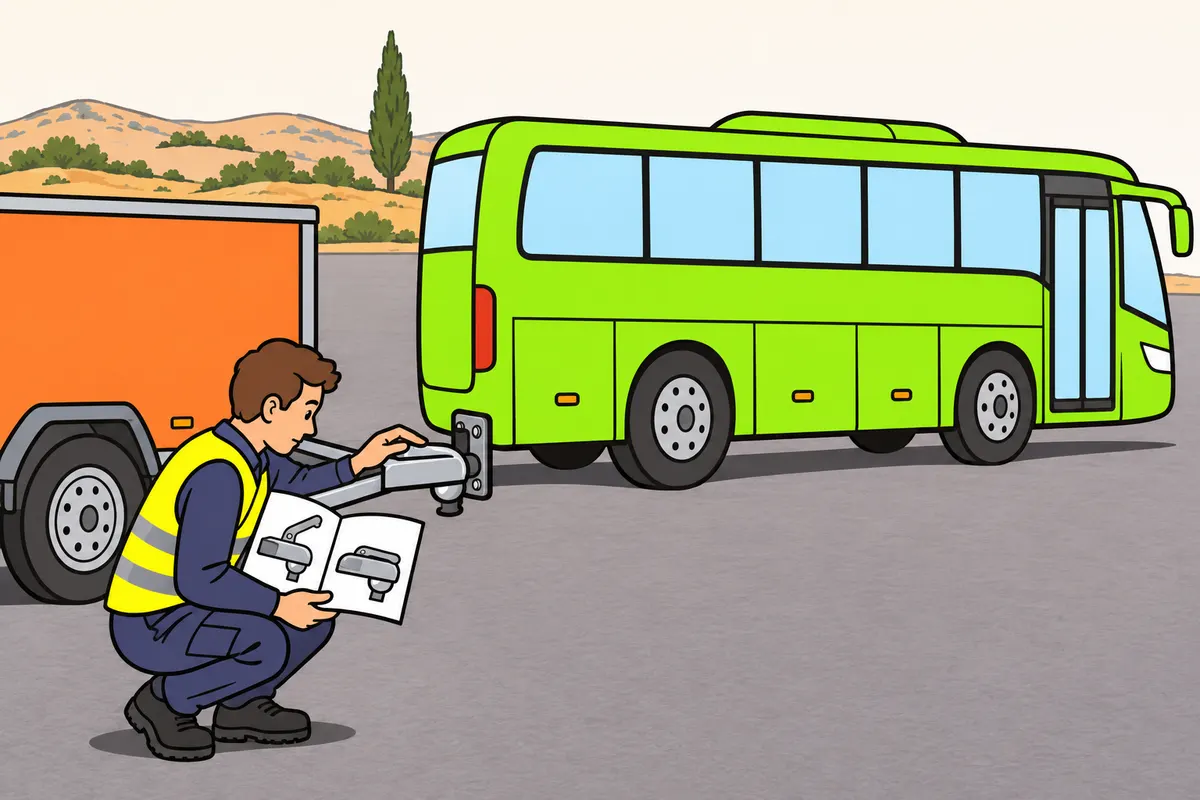
If fitted to your authorised combination, couple the ball head by its manual.
Remember
- Check in the documents that the ball and head are compatible.
- Check that the head captures the ball.
- Check the lever or indicator’s locked position for your model.
- Keep the drawbar support in place until the stated retention check is complete.
Exam trap: Wrong: remove the support because the head rests on the ball. Right: keep it until the manual’s retention check is complete.
Read the full explanation
- If your authorised combination has a ball coupling head, check the documentation to confirm that the ball and coupling head are compatible (see point 2.2).
- Place the coupling head over the ball and complete the coupling movement specified in its manual. Check that the head captures the ball and that the lever or indicator shows the locked state described for that model. Keep the drawbar support in place until you complete the retention check specified for that device. Each type-approved coupling head comes with fitting and operating instructions: follow them. [UN Regulation 55, paragraph 4.6](https://www.boe.es/buscar/doc.php?id=DOUE-L-2026-80273&lang=es).
11Identify the air connections
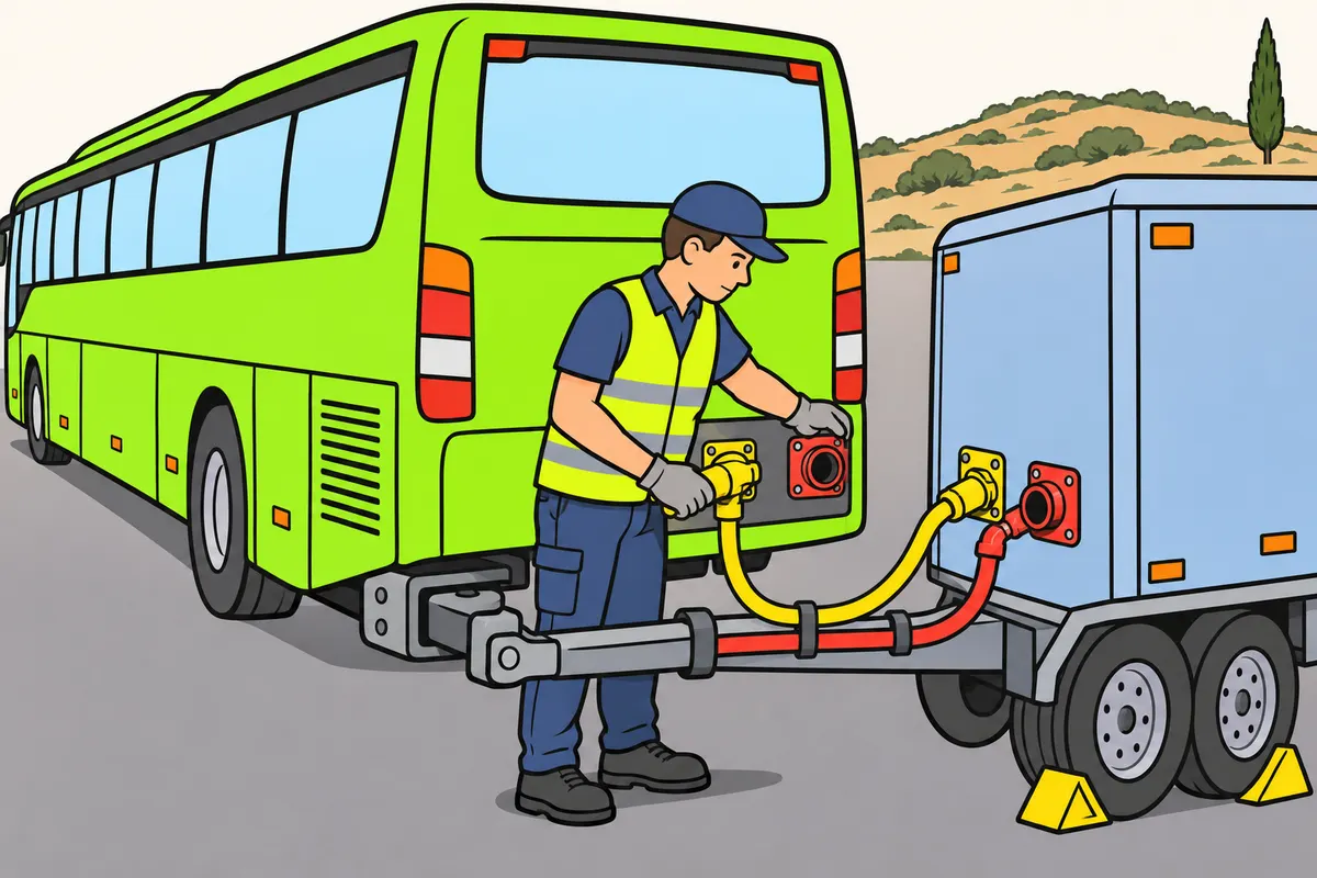
Identify each air line and connect it in the sequence for your system.
| Conventional separate air line | Colour | Connection order |
|---|---|---|
| Control | Yellow | First |
| Supply | Red | Next |
Remember
- Identify connections by their markings; do not swap them.
- Check seals; make sure connections are retained and airtight.
- Do not seal leaks with improvised connections.
- Confirm the sequence in your manual, especially with combined connection blocks.
- If a black button is fitted, check its driving position in the manual.
- In the described system, the black button is normally pulled out for driving.
Exam trap: Wrong: assume the connection is correct because air arrives. Right: check seals, retention, the sequence for your equipment and leaks.
Read the full explanation
- In a conventional two-line air system, identify the red supply line and the yellow control line by their markings; avoid swapping them. You study how the circuit works in «Trailer and combination braking». [BOE, Order of 26 June 1986, annex on pneumatic connections, paragraph 1.4](https://www.boe.es/eli/es/o/1986/06/26/%282%29/dof/spa/pdf).
- Check the seals and contact surfaces before connecting: they must be free of dirt or damage that prevents an airtight seal. Fit the coupling heads without forcing them and check that they are retained. Do not seal a leak with an improvised connection or assume a connection is correct simply because air reaches the trailer.
- After supplying air to the circuit, check that the brake release valve — the black button, if fitted — is in the driving position, normally pulled out in the system described. Resetting may be manual or automatic depending on the equipment. [Fliegl, manual, sections 6.4.3-6.4.4](https://fliegl-agrartechnik.de/fileadmin/datenblaetter_user/EN/Product%20line%20%E2%80%93%20Push-off%20technology/Trailers/Previous%20series/ASW%20push-off%20trailer/Operating%20instructions%20ASW%20push-off%20trailer_EN_3.0.pdf).
- With conventional separate coupling heads, connect the yellow control line first and then the red supply line. Confirm the sequence in your equipment manual, especially if it has a combined connection block. This is a manufacturer's operating procedure. [ROJO Trailer, manual, section 4](https://www.rojotrailer.com/wp-content/uploads/2022/05/Manual-banera-espanol-AluHARD-500-rev3.pdf).
12Electrical and service connections
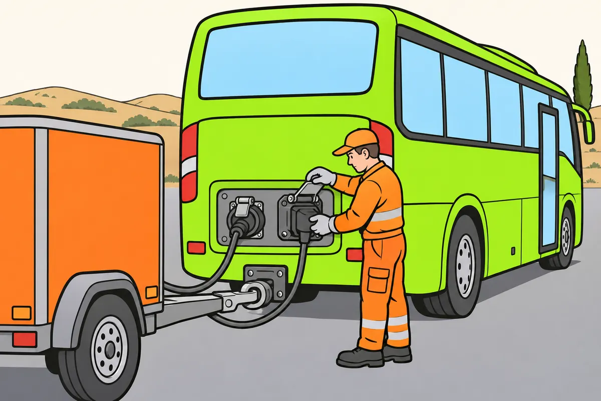
Connect each electrical and other service to its correct socket.
| Connection, if fitted | Function |
|---|---|
| Lighting socket | Lighting and signals |
| ABS or EBS | Electronic braking |
Remember
- Identify sockets by their markings and shape.
- Connect the lights and any electronic braking fitted to your combination.
- Check contacts, covers and retaining parts.
- Hold plugs by their bodies, not by the cables.
- Connect required services and stow those that must remain stored.
- For hydraulic connections, follow the manufacturer’s pressure and disconnection requirements.
Exam trap: Wrong: assume connecting the lights also connects ABS or EBS. Right: identify and connect each service fitted to your combination.
Read the full explanation
- Connect the trailer's lighting and signalling system and any electronic braking connectors fitted to the combination. The lighting socket and the ABS or EBS connection have different functions. Identify each socket by its markings and design, without inserting a connector into another socket because it appears to be a similar size.
- Check plugs, contacts, covers and latches, and hold the connector by its body when inserting or removing it. Do not pull on the cable or force a misaligned socket. A plug may appear to be inserted and come loose with vibration if you have not engaged its retaining mechanism.
- Connect any additional services the equipment needs and stow those that must remain stored. If there are hydraulic lines or other special circuits, follow the manufacturer's pressure and disconnection requirements; a hydraulic connection requires different precautions from an electrical plug.
13Give hoses freedom of movement and support
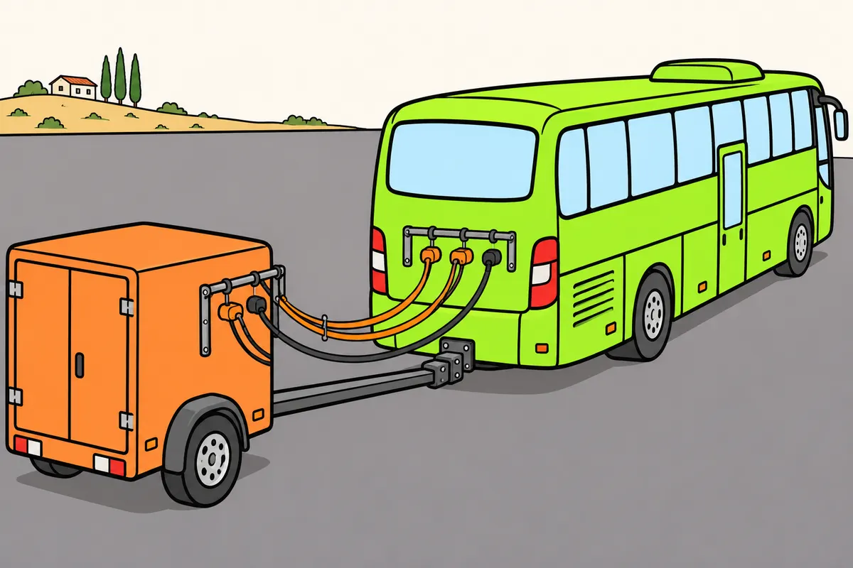
Route and support every cable and hose so it can move safely.
Remember
- Check the route between both ends.
- Leave enough length for turns and suspension movement.
- Keep lines off the ground, away from tyres and clear of trapping points.
- Secure excess length using the supports provided.
- Keep lines away from hot parts and sharp edges.
- Do not tie spiral hoses so tightly that they cannot extend.
Exam trap: Wrong: check hoses only with the vehicles straight. Right: leave room for turns and suspension movement.
Read the full explanation
- Arrange the cables and hoses with enough free length for the expected turns and suspension movements. Check their route between both ends, not just the area visible from one side. A connection that is correct in a straight line can become taut as soon as the bus begins to turn.
- Prevent the lines from dragging on the ground, rubbing against the tyres or becoming trapped between the coupling, drawbar and bodywork. A long loop close to the ground can catch on an obstacle or end up under a wheel during manoeuvres.
- Secure the excess length using the supports provided and keep it away from hot components and sharp edges. A coiled line tied down rigidly can lose its usable extension. Also check the fixings at both ends: they must support the line without concentrating the strain of turning on the electrical contact or air coupling head.
14Breakaway cable and secondary coupling
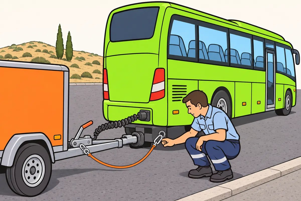
Check the fitted separation safety device and attach it as specified.
| Device, if fitted | Purpose |
|---|---|
| Breakaway cable | Activates the designed brake after accidental separation |
| Secondary coupling | Keeps drawbar off the ground and preserves some steering control |
Remember
- If fitted, attach the breakaway cable at the maker’s stated point.
- Allow turns without dragging or applying the brake by mistake.
- Check the automatic braking device actually fitted to your trailer.
- Do not confuse the breakaway cable with an electrical cable or anti-theft device.
- At MMA up to 1,500 kg without breakaway braking, a secondary coupling is required.
- Check it keeps the drawbar off the ground and preserves some steering control.
Exam trap: Wrong: require this secondary coupling on every heavy trailer. Right: it applies to trailers with MMA not exceeding 1,500 kg and no system to ensure braking if the coupling breaks.
Read the full explanation
- If your trailer has a breakaway cable, attach it to the point specified by its manufacturer and check its route. Its purpose is to activate the braking system designed for accidental separation. Do not confuse it with the electrical cable, an earth connection or an anti-theft device.
- Give the breakaway cable or secondary coupling enough freedom to articulate without dragging, snagging or applying the brake during a normal turn. Check its attachment to the trailer mechanism. [UN Regulation 55, section 4.8.1](https://www.boe.es/buscar/doc.php?id=DOUE-L-2026-80273&lang=es).
- Trailers with an MMA (maximum authorised mass) not exceeding 1,500 kg that have no system to ensure braking if the coupling breaks need a secondary coupling. This must prevent the drawbar from touching the ground and retain some residual steering control. A safety chain is not equivalent to automatic brake activation. [RGV, art. 13.4](https://www.boe.es/buscar/act.php?id=BOE-A-1999-1826#a13).
- If your trailer uses automatic braking on separation, check the device actually fitted and its connections. Its purpose is to ensure that the trailer stops automatically if it becomes uncoupled or the coupling breaks while driving. Do not assume that all equipment does this using the same cable: identify your combination's system. [RGV, art. 12.8.3](https://www.boe.es/buscar/act.php?id=BOE-A-1999-1826#a12).
15Support legs and jockey wheel
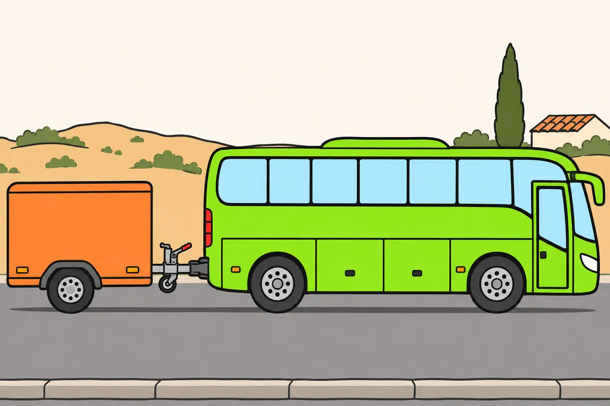
Stow and lock the supports for driving, and set them safely before uncoupling.
| Trailer situation | What you do with its supports |
|---|---|
| Preparing to drive | Retract them after locking the coupling and confirming it bears its intended load |
| Preparing to uncouple | Set them and check they are stable before opening |
Remember
- Retract supports once the coupling is locked and correctly supports the drawbar.
- Check that supports are raised and secured.
- Stow and secure the crank handle in its holder.
- Raise and lock the jockey wheel if fitted.
- Before separating, adjust the support without forcing the drawbar upwards.
- Check the base and lock to prevent folding under load.
Exam trap: Wrong: drive with a support leg down for stability. Right: stow and secure supports before driving.
Read the full explanation
- Retract the trailer supports once the coupling is locked and correctly bears the load it is intended to support. Check the ground clearance and that all moving parts are secured. Their travelling position must allow suspension movement and changes in gradient without a leg touching the ground.
- Stow the crank handle and secure it in its holder. A loose crank handle can strike an obstacle during a turn or a change in gradient. Visually check the final position of the supports and their locking devices. [SAF-HOLLAND, support devices, section 6.5](https://literature1.safholland.com/sites/damedit/literature/FH-LG_Hercules_dropleg_es-DE.pdf).
- If the trailer has a jockey wheel, raise it, retract the assembly and lock its mounting as required for that model. Check that it cannot drop, turn far enough to rub against a component or come loose through vibration.
- The support holds up the part of the trailer that rests on the coupling during coupling. When preparing to separate the vehicles, adjust its extension to take this weight without forcing the drawbar upwards. A tilted base or an incompletely engaged lock can allow the support to fold under load; check the locking mechanism of the model fitted.
16Final walk-round check of the combination
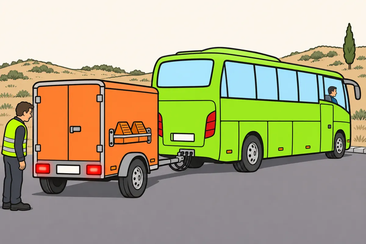
Check the whole combination and remove chocks when it is safe to move.
Remember
- Check the trailer lights while the combination remains immobilised.
- Fix any fault before driving.
- Look for trapped cables, forgotten tools and open covers or compartments.
- Use the coupling diagram as a checklist.
- Remove and stow chocks when the combination can remain secure without them.
- Secure them in their holder so they cannot fall out when moving off.
Exam trap: Wrong: drive over the chocks. Right: remove and store them before moving off, keeping the combination secure.
Read the full explanation
- Once you have completed the connections, check the trailer lights by operating their functions with assistance or using the means available, keeping the combination immobilised. Rectify any fault before driving. [ROJO Trailer, manual, general warnings and driving](https://www.rojotrailer.com/wp-content/uploads/2022/05/Manual-banera-espanol-AluHARD-500-rev3.pdf).
- Carry out a final walk-round check for pinched cables, tools left behind or covers and compartments left open during coupling. Use the coupling diagram as a checklist; the general inspection is covered in «Maintenance and inspection of the vehicle combination».
- Remove the chocks when the combination is ready to move off and you can keep it secure without them; stow them in their designated place. Check that they are secured in their holders so that they cannot fall out as you move off. [RGC, art. 92.3.d](https://www.boe.es/buscar/act.php?id=BOE-A-2003-23514#a92).
17Pressure and testing before moving off
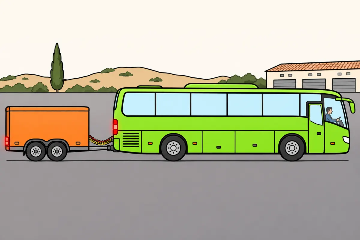
Check the system’s operating state and test the brakes before setting off.
| Check | What it tests |
|---|---|
| Mechanical retention check | The connection resists separation |
| Very low-speed brake test | The brakes respond normally |
Remember
- For air connections, follow the maker’s operating conditions.
- Check warnings and fix leaks before moving off.
- Test brakes very slowly in a safe area, with supports up and chocks removed.
- Release parking brakes when specified; keep the combination held until the test begins.
- Move off smoothly; stop safely for knocks, warnings or abnormal movement.
- Carry out the same checks when empty or travelling a short distance.
Exam trap: Wrong: memorise a pressure suitable for every combination. Right: follow your manufacturer’s operating requirements and check for faults.
Read the full explanation
- If you have air connections, wait until the system reaches the operating conditions specified by the manufacturer and check the pressure and braking warnings. Do not memorise a single pressure for every bus and trailer. An apparently airtight connection does not by itself prove that you have the reserve needed to drive safely.
- Check for leaks using the methods provided, paying attention to leaks at the connections you have just made. Do not search for a leak by putting your hands into mechanisms that may operate. If you hear a persistent leak or notice an abnormal pressure drop, immobilise the combination and rectify the fault before considering it ready.
- Carry out a functional braking test at very low speed in a safe area, once you have retracted the supports and removed the chocks in accordance with the procedure. Check that the combination responds normally and stop if you notice jerking or abnormalities. This test checks braking; you check mechanical retention at the coupling. Release the trailer parking brake at the prescribed stage before moving off, keeping the combination held using the appropriate controls until you begin the test.
- Move off smoothly and observe the trailer and its connections. If you notice an abnormal knock at the coupling, a warning or an unexpected movement, stop safely and inspect. You must carry out the same coupling checks with an empty trailer and for a short journey.
18Prepare to uncouple
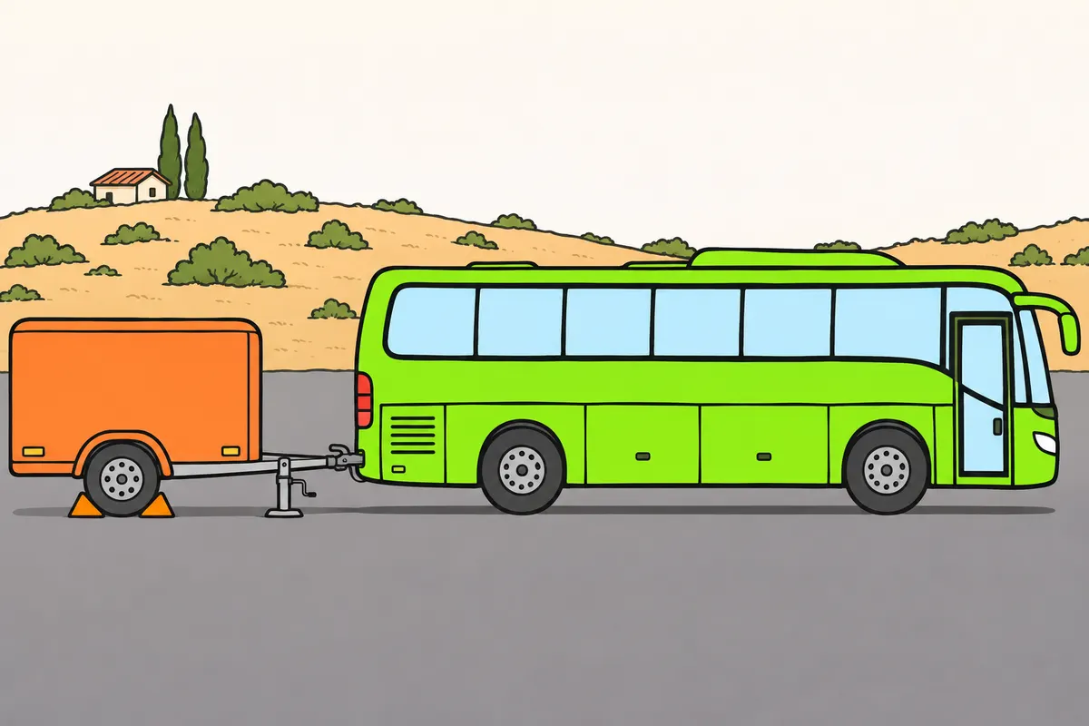
Park and support the trailer so it stays stable when separated.
Remember
- Choose firm ground where the detached trailer will stay stable and allow recoupling.
- Check the luggage will not make it unstable when separated.
- Leave the combination aligned, without unnecessary strain.
- Before disconnecting, check that the trailer parking brake and chocks hold it.
- The bus’s kerb position will not secure the detached trailer.
- Lower the supports and make sure they sit firmly before separating.
Exam trap: Wrong: disconnect before securing the trailer. Right: apply its parking brake, check it cannot move and support it first.
Read the full explanation
- Choose where to separate the vehicles with the trailer's position when detached and your ability to recouple it in mind. Avoid placing supports on edges, unstable covers or surfaces that may give way. With luggage on board, take particular care to check that the load's position does not compromise stability when the support from the bus is removed.
- Leave the combination aligned and without unnecessary strain on the coupling. Before disconnecting, check that the trailer's parking brake and chocks can hold it on their own. Resting a bus wheel against the kerb does not secure the trailer once detached; holding it in place depends on its own means of immobilisation.
- Lower the drawbar support or the supports fitted to the trailer and check that they rest securely on the ground. Adjust the height so that you can separate the vehicles without the drawbar dropping or the support mechanism being overloaded. If the vehicle's suspension is involved, follow its procedure while keeping everyone out of areas that may lower or move.
19Disconnect before moving the bus away
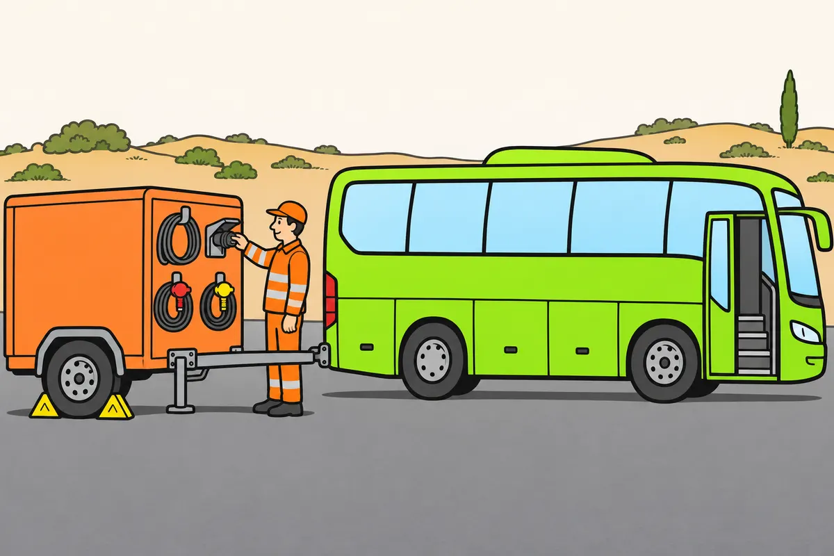
Disconnect and stow every service before moving the bus away.
Remember
- Immobilise and support the trailer before disconnecting.
- With conventional separate air heads, disconnect red first, then yellow.
- Keep your face away from air outlets and protect the connections.
- Release plug retainers and hold plugs by their bodies.
- Detach any breakaway cable or secondary coupling at the stage specified.
- Stow connections so they cannot drag.
Exam trap: Wrong: move forwards with a hose connected because it looks long enough. Right: disconnect and stow all services before moving the bus away.
Read the full explanation
- With the trailer immobilised and supported, disconnect the service connections according to the equipment procedure. With conventional separate air coupling heads, disconnect the red supply line first and then the yellow control line. Keep faces and eyes away from air outlets and protect the mating surfaces from dirt. [ROJO Trailer, manual, section 8](https://www.rojotrailer.com/wp-content/uploads/2022/05/Manual-banera-espanol-AluHARD-500-rev3.pdf).
- Disconnect the electrical and electronic braking plugs by releasing their locking devices and holding the plug bodies. Fit caps and guards where appropriate. Do not leave a line connected because it seems long enough for the bus to move forward: as the vehicles separate, it can be torn from its mounting or damage other components.
- On systems with a breakaway cable or secondary coupling, release them at the stage specified for uncoupling, after securing the trailer. Stow them so that they do not drag. Do not move forward to break a cable or pull a chain taut: these are safety devices, not tools for completing a normal separation.
20Open the latch and separate under control
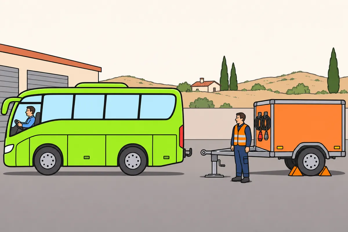
Open the coupling only after the trailer is secured, supported and disconnected.
Remember
- Check immobilisation, supports and disconnection before opening.
- Operate the latch from the designated safe position.
- Keep feet clear of the coupling head and hands clear of the pin’s path.
- If it will not open, secure both vehicles and investigate without hitting or forcing.
- Separate slowly and check that the support holds the drawbar.
- Stop if the support sinks or tilts, or the trailer moves.
Exam trap: Wrong: move the bus away abruptly so the trailer settles. Right: separate slowly and watch the supports and wheels.
Read the full explanation
- Once you have completed the preparations for separation, release the safety lock and open the retaining mechanism in the order given in the manual. Operate the lever from the designated safe position and keep clear of the space into which the drawbar can fall or swing. Do not place your feet under the coupling head or your hands in the path of the pin.
- If the latch does not open, investigate the cause with both vehicles secured. There may be tension in the coupling or a fault in the mechanism; do not hammer it, force it or keep the safety lock disabled as a solution. Follow the manual for any manoeuvre to relieve the load on the coupling, and keep everyone out of the danger zone.
- Separate slowly, checking that the support holds the drawbar and that the wheels remain stationary. If the support sinks or tilts, or the trailer starts to move, stop the operation and restore safe conditions according to the equipment procedure. Do not move the bus away abruptly, trusting that the trailer will settle by itself.
21Check the detached trailer
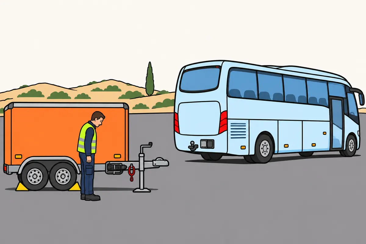
Check both the parked trailer and the bus before leaving the area.
Remember
- Check that the supports hold the trailer stable with its remaining luggage.
- Correct continuing sinking or tilting before leaving it parked.
- Protect connectors; stow cables, chains and drawbar without creating obstacles.
- Keep recoupling controls accessible.
- Check that no cables or hoses hang from the bus.
- Check the coupling is set for driving without a trailer.
Exam trap: Wrong: check only the detached trailer. Right: also check the bus’s lines, accessories and coupling.
Read the full explanation
- After moving the bus away, check how the supports sit on the ground and the angle of the trailer under the weight of the luggage still on board. If it continues to sink or tilt, correct the situation before leaving it parked. Keep the area clear while checking that the ground bears the load from the support stably.
- Check that the connectors are protected and that the drawbar, breakaway cable and chains are stowed without creating obstacles. Keep the controls you need for recoupling accessible. Leave the equipment in a condition that allows you to identify it and prepare for the next approach without handling parts under an unexpected load.
- Before driving the bus on its own, inspect its stowed lines and accessories. Check that no cables or hoses hang down and that the coupling is in the specified position for driving without a trailer. Include both the parked trailer and the bus you are about to move in your final check.
22What to remember for the exam
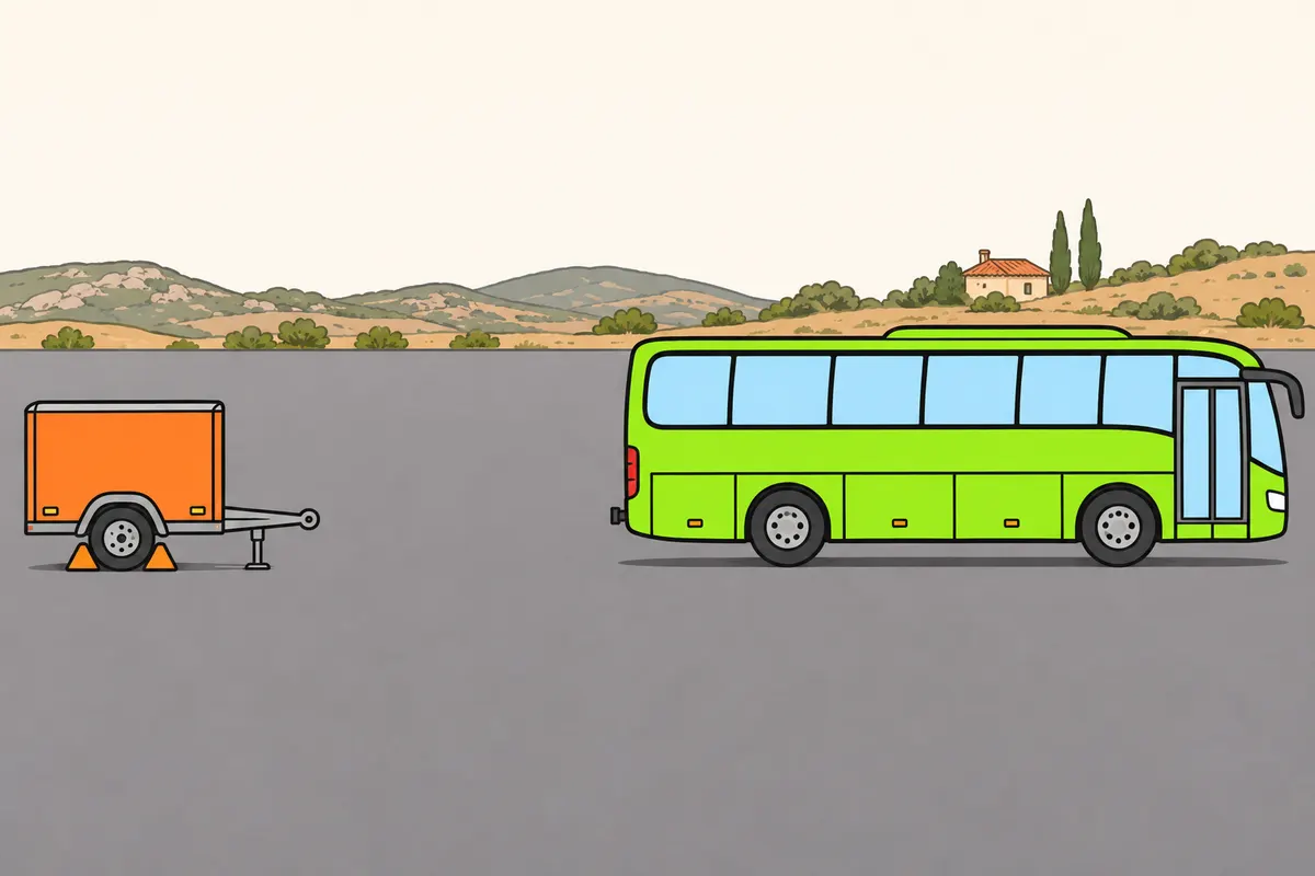
In manoeuvre M, uncouple, reposition the bus and couple again safely.
Remember
- Immobilise the combination before uncoupling.
- Leave the bus beside the trailer and out of line.
- Keep the trailer immobilised; position the bus ahead, at least 10 metres away.
- Reverse to couple; you may get out once during approach to check.
- For non-automatic couplings, you may align the drawbar manually with both vehicles immobilised.
- Complete connections and safety locks; stow used chocks and retract supports as appropriate.
Exam trap: Wrong: apply the exercise distance to every coupling operation. Right: the minimum 10 metres applies to the exam manoeuvre.
Read the full explanation
- In manoeuvre M of the D+E test, immobilise the combination, uncouple and leave the bus alongside the trailer, out of line with it. Keep the trailer properly immobilised; then drive the bus forward to position it in front of the trailer, at least 10 metres away, and reverse to couple up. This distance applies to the test exercise. [RGCond, Annex VI, manoeuvre M](https://www.boe.es/buscar/act.php?id=BOE-A-2009-9481#anvi).
- Complete the lighting connections and all other coupling and safety connections, stow the chocks you have used and retract the supports as appropriate. During the reversing approach, Annex VI allows you to get out once to carry out checks and, if the coupling is not automatic, to align the drawbar manually. [RGCond, Annex VI, manoeuvre M](https://www.boe.es/buscar/act.php?id=BOE-A-2009-9481#anvi).
Couple the bus trailer
Reference sequence for a drawbar and towing eye or a ball coupling head; use the manual to identify the specific controls.
- Choose firm ground, clear passengers from the area and immobilise the trailer with its parking brake; identify the red control and the black brake-release control, if fitted.
- Check compatibility, components, brakes and supports; align the bus and adjust the drawbar height.
- Approach slowly, stop and immobilise the vehicles before working on foot.
- Couple and check seating, closure, safety lock and indicators; carry out the prescribed mechanical check.
- Connect the electrics and any braking services fitted; with a conventional air system with separate lines, connect yellow before red, as specified in the manual. Check that the black brake-release button is in the driving position specified for the equipment.
- Attach and check the appropriate breakaway cable or secondary coupling.
- Retract and lock the jockey wheel, support legs and winding handles; check the routing of the lines.
- Carry out the final walk-round check, test the lights and check pressure and warnings where applicable; remove and stow the chocks when you can keep the combination secure.
- Release the trailer parking brake when appropriate and test the brakes at very low speed in a safe place before setting off.
Uncouple while maintaining support and immobilisation
Give the trailer independent stability and restraint before releasing the coupling.
- Choose ground capable of bearing the weight and secure the bus and trailer against movement.
- Apply the trailer parking brake using its own control — red in the system described — and fit the necessary chocks; do not use the black button to release the brakes.
- Lower the drawbar support or jockey wheel and check that it rests securely and can support the trailer during separation.
- Disconnect and stow the service connections as required by the equipment; with a conventional air system with separate lines, disconnect red before yellow.
- Detach and stow the breakaway cable or secondary coupling at the stage specified in the procedure.
- Release the safety lock and latch in the order specified in the manual.
- Release the towball or towing eye and slowly move the bus away, watching the support and stability.
- Check the detached trailer and the stowed accessories on the bus before finishing.
Manoeuvre M in the D+E exam
Outline of the exercise in Annex VI of the Reglamento General de Conductores (General Driver Regulations).
- Immobilise the combination and uncouple, leaving the trailer immobilised and supported as required by its equipment.
- Position the bus beside the trailer, out of line with it.
- Drive forwards to position it at least 10 metres in front.
- Reverse towards the trailer and couple it; you may get out once during this approach to check and align the non-automatic drawbar.
- Connect the coupling and safety components, retract the supports and stow the chocks used to leave the combination ready to drive.
Finished this module?
Mark it as read and you will see your progress on the theory list.