
Theory · D Licence - Bus · Module 14 of 18
Bus brakes and retarders
You will learn about the functions of the brakes, the path of compressed air and the bus warning systems. You will learn about ABS, EBS, retarders and how they work with the accelerator, as well as what to do in the event of faults, long descents or reduced braking effectiveness. You will also study braking on a light trailer permitted with a D licence.
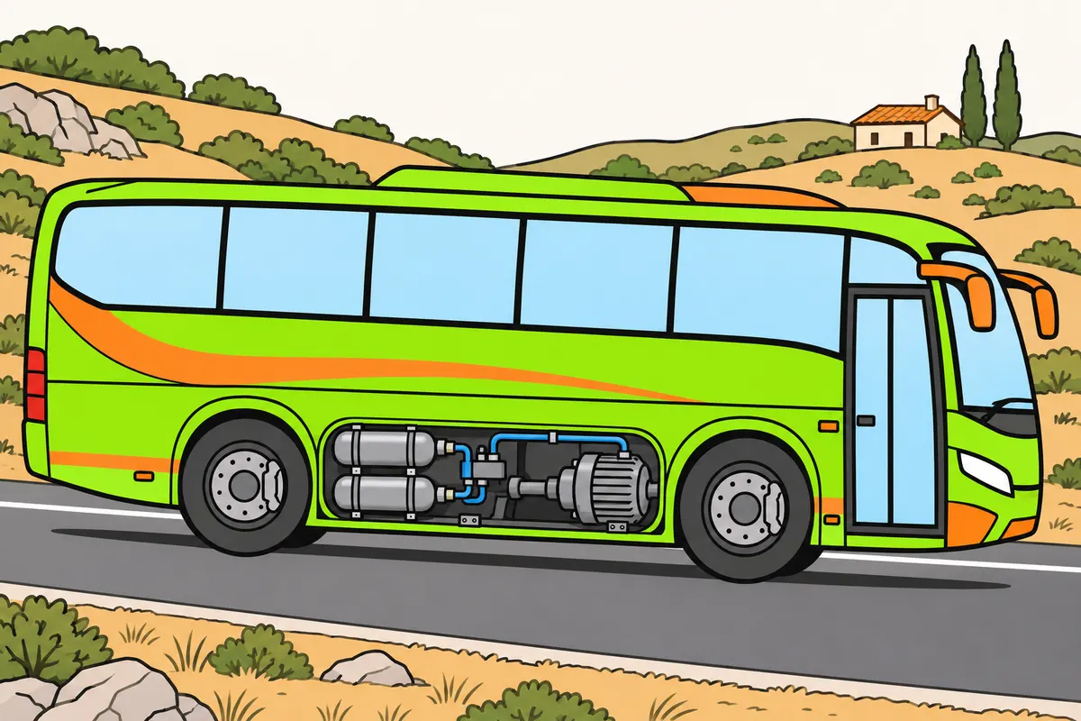
1Three braking functions
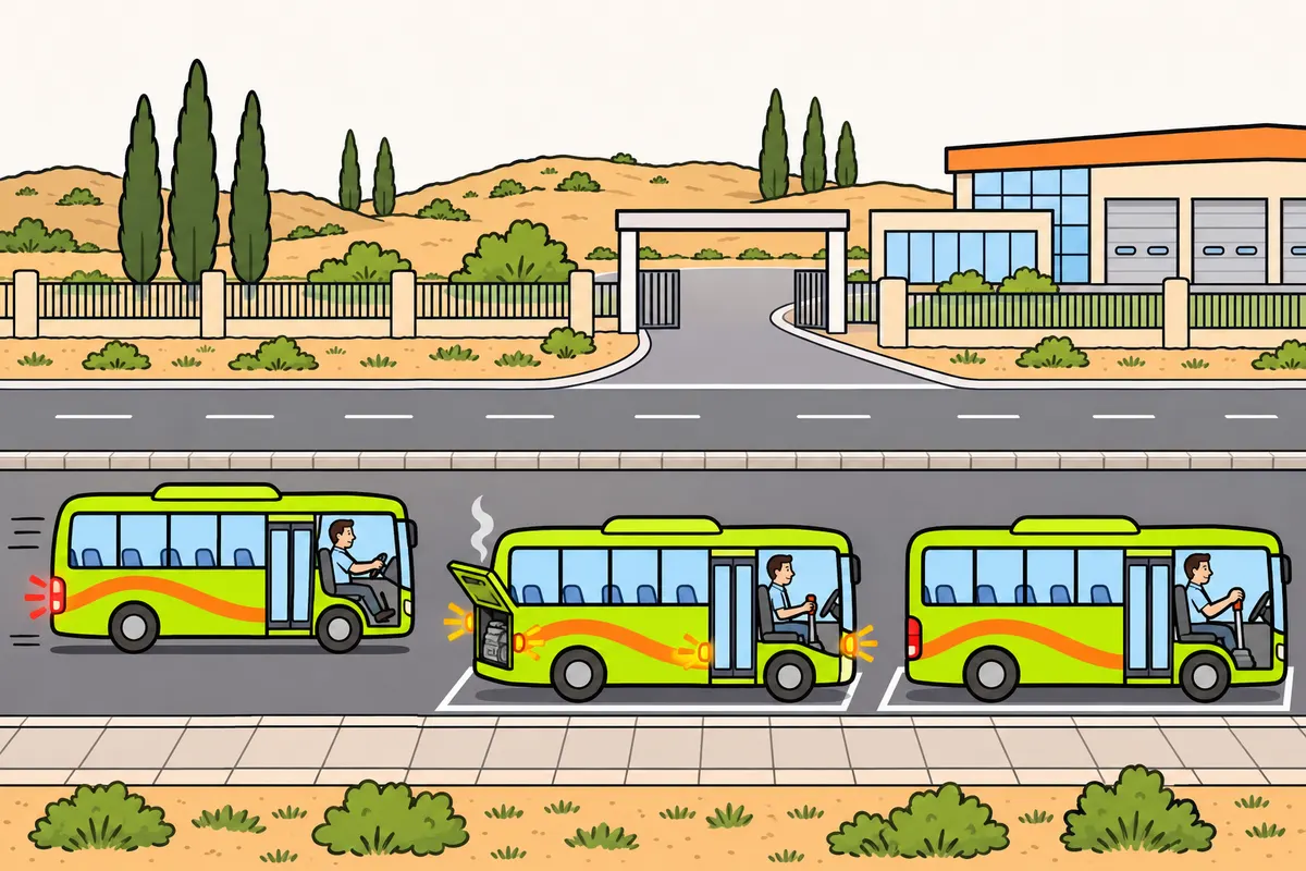
You use each braking function for a different purpose.
| Function | What you use it for |
|---|---|
| Service | You control speed |
| Secondary brake | You stop if the service brake fails |
| Parking | You keep the bus stationary |
Remember
- Learn how each brake works on your bus.
- You can have disc brakes operated by air.
- Distinguish the braking function from how you operate the brake.
Exam trap: Wrong: you think service, pneumatic and disc name the same thing. Right: they describe a function, how it is operated and its friction mechanism.
Read the full explanation
- The service brake controls your movement; the secondary brake allows you to stop if the service brake fails; the parking brake keeps the bus stationary. [RGV, art. 12.8](https://www.boe.es/buscar/act.php?id=BOE-A-1999-1826#a12).
- The three functions can share components through circuits and controls designed for that purpose. You must know how each function works on your bus.
- The function, control and braking component describe different aspects. Service is a function; pneumatic describes how you transmit the action using air; disc or drum identifies the mechanism that creates friction. A bus can have pneumatically operated disc brakes without any contradiction.
2Service brake and progressive application
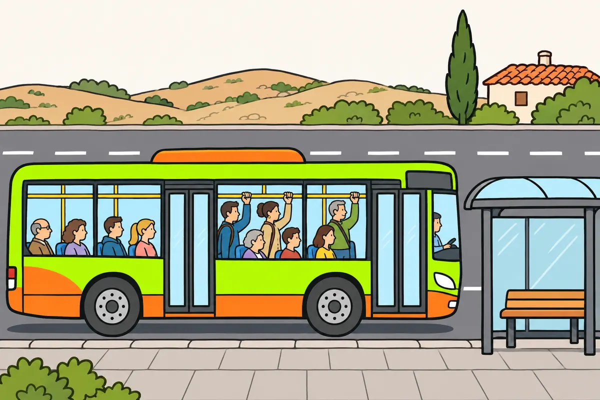
Adjust your pedal pressure to brake as the situation requires.
Remember
- For a planned stop, increase and reduce pressure gradually.
- Avoid jolts that unbalance your passengers.
- In immediate danger, brake as firmly as necessary.
- Do not rest your foot continuously on the pedal.
- This avoids unnecessary heat and wear.
Exam trap: Wrong: you brake weakly in an emergency to stay smooth. Right: brake as needed and keep control.
Read the full explanation
- Using the service brake pedal, you request the bus's normal braking. You can modulate it, increasing or reducing its intensity to suit the situation. The ability to modulate it is part of its regulatory definition. [RGV, Annex VIII, section 1.2.1](https://www.boe.es/buscar/act.php?id=BOE-A-1999-1826#anviii).
- When you plan to stop, you must apply the brake progressively and adjust the pressure as you approach the stop. This reduces passengers' movements, especially for those travelling standing, and helps you stop at the chosen point without jolts.
- Smoothness does not mean braking weakly when there is immediate danger. If you need to make an emergency stop, you must apply the braking force needed and keep control; anticipation is what allows you to avoid many heavy braking applications during normal service.
- You must not drive with your foot resting continuously on the pedal. An unintended application can keep the brakes working, generate heat and wear, and reduce the thermal reserve you need for a later braking manoeuvre or descent.
3Secondary braking and circuit failure
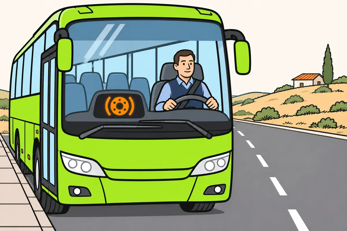
If service braking fails, use the available braking to stop safely.
Remember
- You can adjust your secondary (emergency) brake (freno de socorro) force.
- Do not expect the effectiveness of a fully working system.
- A circuit that keeps pressure can still provide braking.
- Stop when a fault occurs; do not finish the route.
- Use parking controls for secondary braking only as the manufacturer allows.
- Do not test faults by braking hard in traffic.
Exam trap: Wrong: you apply the parking brake suddenly while moving. Right: if graduated secondary braking is available, follow the manufacturer’s procedure.
Read the full explanation
- The secondary braking system must stop you within a reasonable distance if the service brake fails and allow you to modulate its action. This does not promise that it will be as effective as when all circuits are intact. [RGV, Annex VIII, section 1.2.2](https://www.boe.es/buscar/act.php?id=BOE-A-1999-1826#anviii).
- In a system with several circuits, the part that retains pressure may provide residual braking when another circuit fails. If you receive a warning, stop safely; having redundancy does not justify completing the route with a brake fault.
- If the parking brake control allows you to apply the secondary brake gradually, follow the manufacturer's procedure. Applying it abruptly while moving can lock the wheels or destabilise the bus.
- If the pedal response changes or the bus veers when you brake, reduce the risk and find a safe place to stop. Avoid testing the fault with hard braking in traffic.
4Parking and securing the vehicle
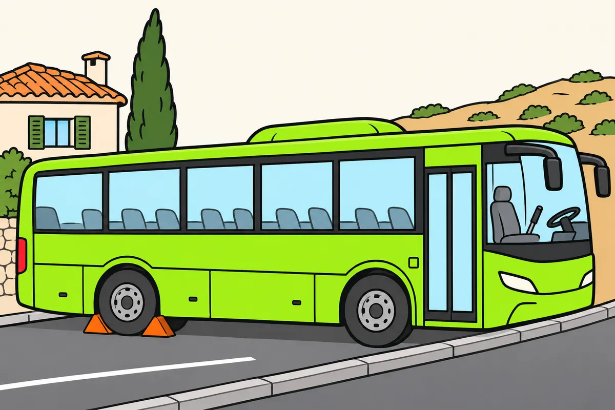
Before leaving your seat, secure the bus with the parking brake.
Remember
- Secure your bus before leaving your seat.
- The parking brake keeps your bus stationary even without a driver.
- The holding force is mechanical.
- In a spring brake, the spring provides this force.
- If fitted, check the manual for the door-linked brake’s conditions of use.
- The stop brake can hold passengers, but it cannot secure the bus.
Exam trap: Wrong: you leave the bus held by its stop brake. Right: use the parking brake; a door-linked hold may not provide the function needed to leave the driving seat.
Read the full explanation
- The parking brake must keep the vehicle stationary even without a driver, maintaining the braking force through a purely mechanical device. In a spring brake, the spring provides this holding force. [RGV, Annex VIII, section 1.2.3](https://www.boe.es/buscar/act.php?id=BOE-A-1999-1826#anviii).
- When you leave the driving position, you must secure the bus; the procedures and use of chocks on a slope are explained in “Manoeuvres with the bus”. [RGC, art. 92.3](https://www.boe.es/buscar/act.php?id=BOE-A-2003-23514#a92).
- If your bus has a stop brake or automatic hold linked to the doors, consult the manual for its conditions of use. It can hold the vehicle while passengers board without providing the parking function you need to leave the driving seat.
5Discs, drums and heat
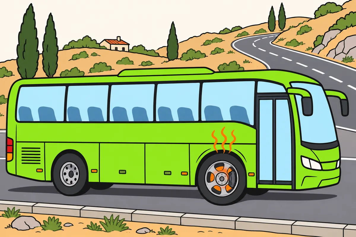
Braking produces heat, so your brakes can weaken even with enough air.
| Brake | Parts you should recognise |
|---|---|
| Disc | Caliper and pads acting on the disc faces |
| Drum | Shoes pressing against the inside surface |
Remember
- Your brakes need to release the heat they build up.
- A continuous descent can make them very hot.
- Your pressure gauge shows the air reserve.
- It does not show how much heat the brakes can handle.
- Report unusual noises, vibrations, smells or braking responses.
Exam trap: Wrong: you think enough air guarantees effective braking. Right: too much heat can reduce braking effectiveness.
Read the full explanation
- In a disc brake, the calliper contains the pads that press against the disc faces. In a drum brake, the shoes press against its inner surface.
- When you brake through friction, you convert the energy of movement into heat. The disc or drum and its friction materials need to dissipate it; a single braking application and a continuous descent create different thermal stresses, even when you use the same pedal and pneumatic pressure.
- You may have sufficient air pressure and still lose braking effectiveness because the friction components overheat. The pressure gauge tells you about the pneumatic reserve, not the wheels' ability to dissipate heat.
- Investigate noises, vibrations, unusual smells, wear indicated on the dashboard or differences in response. Maintenance preserves effectiveness in both dry and wet conditions; you must not wait for a descent to discover that a brake is working badly.
6The path of air through the system
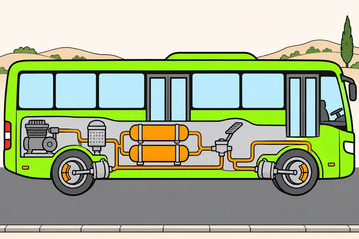
You use compressed air to operate the wheel brakes.
Remember
- Follow the path: production, treatment, storage, distribution and chambers.
- The compressor produces compressed air.
- The reservoirs store the reserve.
- In a conventional system, your pedal regulates pressure sent to the chambers.
- Friction between brake parts slows the wheels.
- Avoid pressing and releasing the pedal repeatedly without need: you use up air.
Exam trap: Wrong: you think the reservoir produces air. Right: the compressor produces it; the reservoir stores it.
Read the full explanation
- In a pneumatic brake, the functional path includes air production, treatment, storage, distribution and operation of the brake chambers. Air transmits energy to operate the brakes; friction between the pads and discs or shoes and drums produces braking at the wheels.
- The compressor produces compressed air and the reservoirs store it. The reserve meets braking demands while the system replenishes the air.
- In a conventional system, the pedal controls valves that meter the pressure sent to the chambers. The force at the wheels comes from pneumatic pressure.
- Each application and release of the brake can use air from the reserve. Avoid operating the pedal repeatedly without need, especially when the compressor is not producing air.
7Compressor and pressure regulation
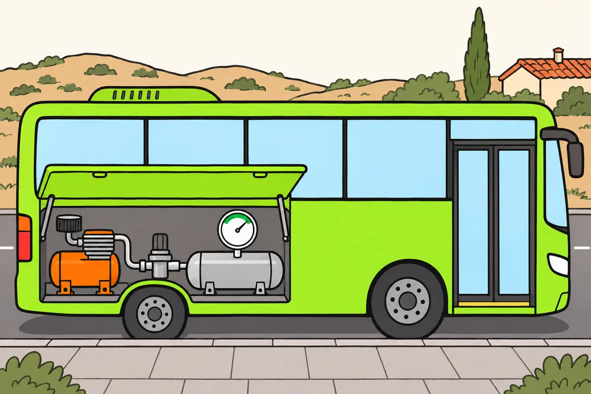
Check the pressure specified by your bus manufacturer.
| Pressure | What you should distinguish |
|---|---|
| Operating pressure | Shows the working reserve |
| Alarm threshold | Warns of a situation requiring action |
Remember
- The compressor supplies compressed air to the circuit.
- The governor stops and restarts charging according to pressure.
- Distinguish this normal cycle from a continuous air leak.
- Not every bus drives its compressor in the same way.
Exam trap: Wrong: you confuse operating pressure with the alarm threshold. Right: check both values and their functions in the manual.
Read the full explanation
- The compressor draws in air and supplies it to the circuit under pressure. In a conventional installation, it may be driven by the engine; you must know the layout and operating conditions of the equipment on your bus.
- The regulator controls the circuit charge within its operating range. When the specified pressure is reached, it orders useful air production to stop or unload; when pressure falls sufficiently, charging resumes. A continuous air leak requires inspection even if the regulator continues to order charging.
- The valve that limits maximum pressure protects the circuit against excess pressure; its setting must match the installed system and be maintained in accordance with the manufacturer’s instructions.
- Consult your bus manual for the system pressure ranges and charging conditions. The operating value and the warning threshold serve different purposes: one describes the working reserve and the other warns of a situation that requires action.
8Air dryer, moisture and draining
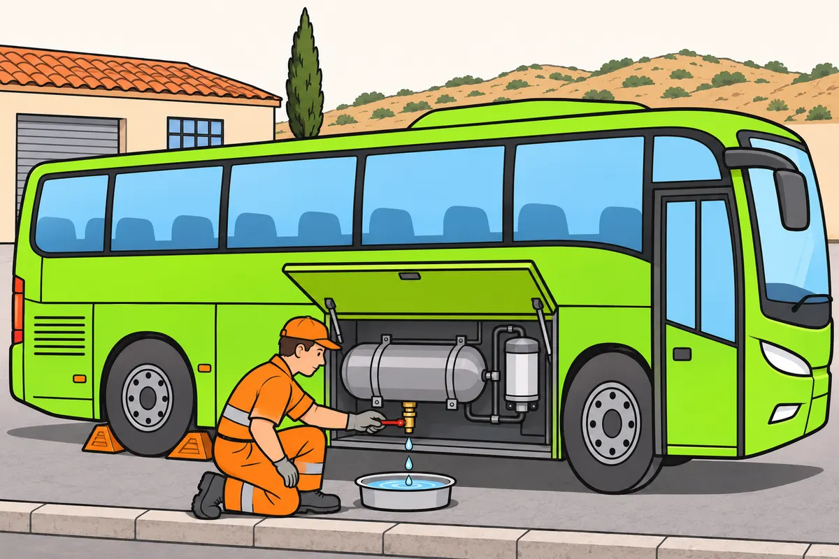
Maintain your air treatment system to prevent moisture and circuit damage.
| Device | What you remove with it |
|---|---|
| Filter | Impurities |
| Dryer | Moisture from air |
| Reservoir drain | Accumulated water |
Remember
- Moisture can form ice in the lines.
- Follow manufacturer maintenance instructions; draining may be manual or automatic.
- Secure your bus before emptying reservoirs.
- Do not add alcohol or antifreeze on your own initiative.
- Report abnormal water build-up.
- Removing water does not repair the cause of its build-up.
Exam trap: Wrong: you confuse reservoir draining with hydraulic brake bleeding. Right: draining removes accumulated water; hydraulic bleeding removes air bubbles.
Read the full explanation
- Moisture in the air can condense as it is compressed and cools. The air dryer removes moisture and reduces the risk of ice forming in the pipes. [DGT, Manual VIII, air treatment](https://sede.dgt.gob.es/export/sites/dgt/.galleries/permisos-de-conducir/certificacion-aptitud-profesores-formacion-vial/2024/Manual-VIII-Mecanica-2024.pdf).
- The filter retains impurities and the air dryer treats moisture. They may be integrated into one treatment unit. Abnormal quantities of dirt, water or oil can damage valves and other circuit components.
- Draining an air reservoir means evacuating the condensate through the designated device. Follow the manufacturer’s maintenance schedule, using manual or automatic draining according to the installation; you cannot set the same frequency for every bus or empty reservoirs without first securing the vehicle.
- Use only products and procedures compatible with the installed air treatment system. Adding alcohol or antifreeze on your own initiative can damage a system with a cartridge air dryer.
- Report an abnormal accumulation of water so that the air treatment system can be checked. Draining the condensate does not fix its cause; hydraulic bleeding expels bubbles from a different type of circuit.
9Reservoirs and circuit protection
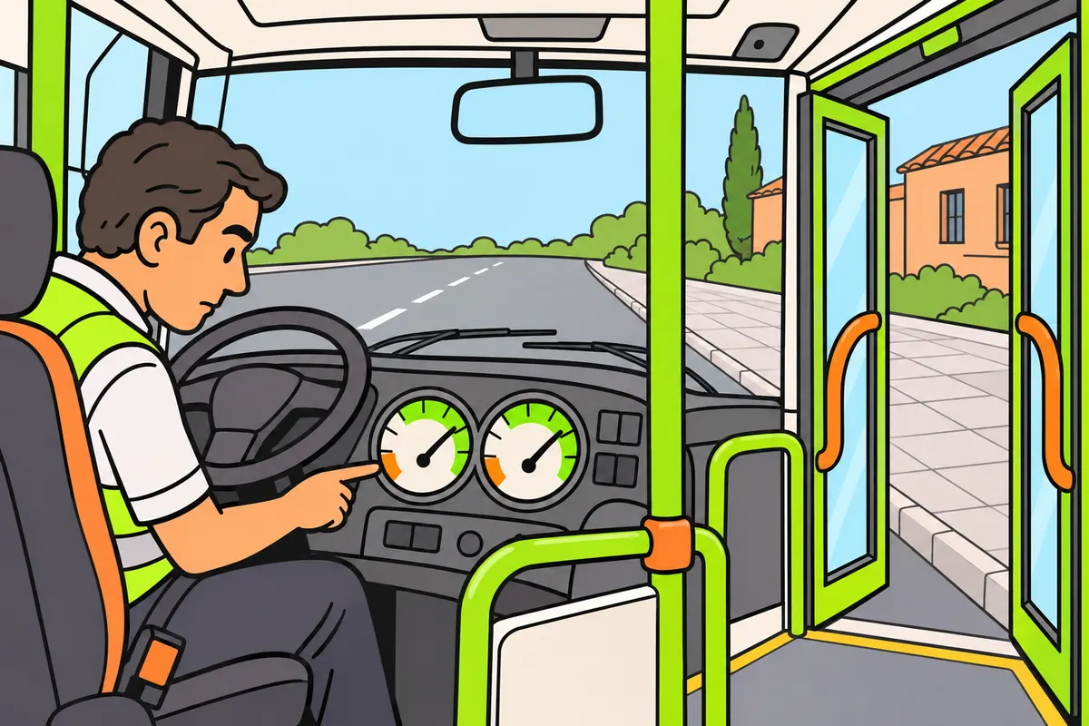
Check your brake air reserve even if the doors and suspension work.
| Component | Function you should recognise |
|---|---|
| Reservoir | Stores compressed air |
| Brake chamber | Turns pressure into movement and force |
Remember
- The non-return valve lets air through and prevents it flowing back.
- Multi-circuit protection helps isolate a circuit losing pressure.
- The remaining reserve lasts according to the air available.
- Your brakes may share air production with doors and suspension.
- Check brake pressure directly before setting off.
Exam trap: Wrong: you set off because the doors work. Right: check brake pressure; working doors do not prove it is sufficient.
Read the full explanation
- The reservoirs maintain a supply of compressed air for braking and other intended functions. The reservoir stores energy; the brake chamber converts the pressure it receives into movement and actuating force.
- The non-return valve allows air to pass in one direction and prevents it from flowing back. Its function is to keep the reserve where it belongs.
- The multi-circuit protection valve distributes the air and helps isolate a circuit that loses pressure. A four-way valve protects the remaining reserves, whose duration depends on the available air.
- The brakes may share air production with the suspension, doors or other consumers, with protections and priorities specified by the manufacturer. Check the brake pressure directly; the doors working or the body reaching its normal height is not enough to authorise departure.
10Pressure gauges and low-pressure warning
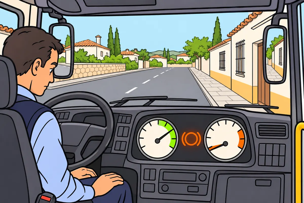
Read every pressure indicator and stop safely if pressure is too low.
Remember
- Check each circuit, even when another has enough pressure.
- Before departure, wait for specified pressure and for warnings to clear.
- Follow your bus procedure.
- Do not accelerate against a spring brake held on by low pressure.
- If a warning appears while driving, seek a safe stop.
- Check the manual for pressure, warnings and charging time.
Exam trap: Wrong: you wait for the springs to brake automatically. Right: respond to low-pressure warnings and seek a safe stop.
Read the full explanation
- Read all the pressure gauges for the brake circuits shown on the dashboard. If there are two needles or two readings, do not assess only the higher one: one circuit may have an adequate reserve while another has insufficient pressure.
- Before moving off, you must wait until the specified operating pressure is reached and the warnings clear in accordance with the vehicle’s procedure. If a spring brake remains applied because of insufficient pressure, wait for the system to charge correctly without trying to force the vehicle to move with the accelerator.
- A visual or audible low-pressure warning requires an immediate and safe response. If it appears while you are driving, look for a safe place to stop using the means available; do not wait for the springs to apply automatically or for the pedal to stop braking altogether.
- Consult the manual for the working pressure, warning threshold and permitted charging time. The ITV (vehicle roadworthiness test) checks the pressure, warnings and system recovery. [RD 920/2017, Annex I, sections 1.1.3 and 1.1.4](https://www.boe.es/buscar/act.php?id=BOE-A-2017-12841#ani).
11Chambers and quick release
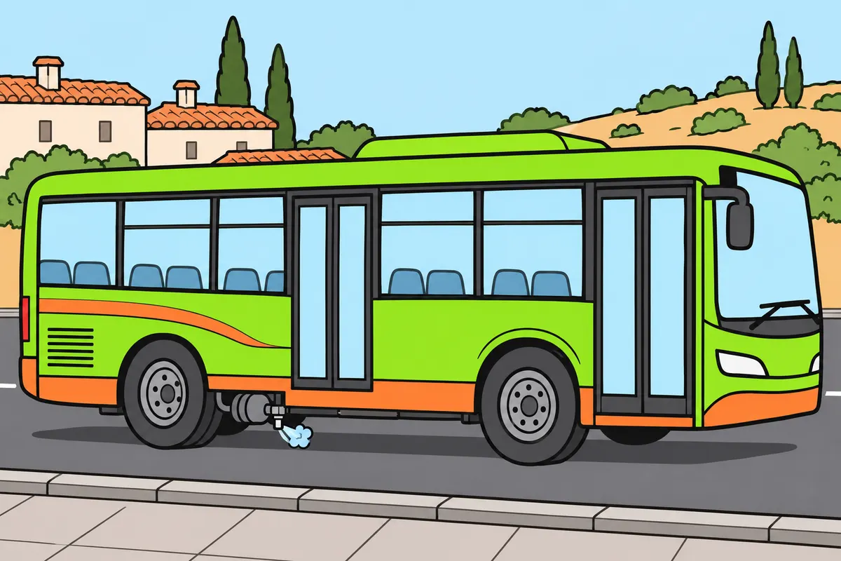
Understand how air enters the chambers and escapes when you stop braking.
Remember
- In a conventional service chamber, air moves a diaphragm or piston.
- When you stop braking, air escapes and the mechanism returns.
- Quick release helps the brake release.
- A relay valve uses air from a nearby reservoir.
- Distinguish the braking command from the reserve supplying air.
- Investigate persistent leaks with pressure loss, following the manufacturer’s procedure.
Exam trap: Wrong: you think every air discharge means a fault. Right: a brief intended discharge can be normal; investigate persistent leaks.
Read the full explanation
- In a conventional service chamber, air pressure moves a diaphragm or piston and operates the brake mechanism. When you stop applying the brakes, air is released and the mechanism returns.
- The quick-release valve allows air to escape close to the chambers when you stop braking. Its function is to help release the brake.
- Relay valves allow air from a nearby reservoir to be used in response to a braking command. In the bus’s long circuits, the control signal reaches the valve, which uses the nearby reserve to supply the required flow.
- A brief release of air provided for by the system may be normal. Investigate persistent leaks involving pressure loss in accordance with the manufacturer’s procedure.
12Spring brakes
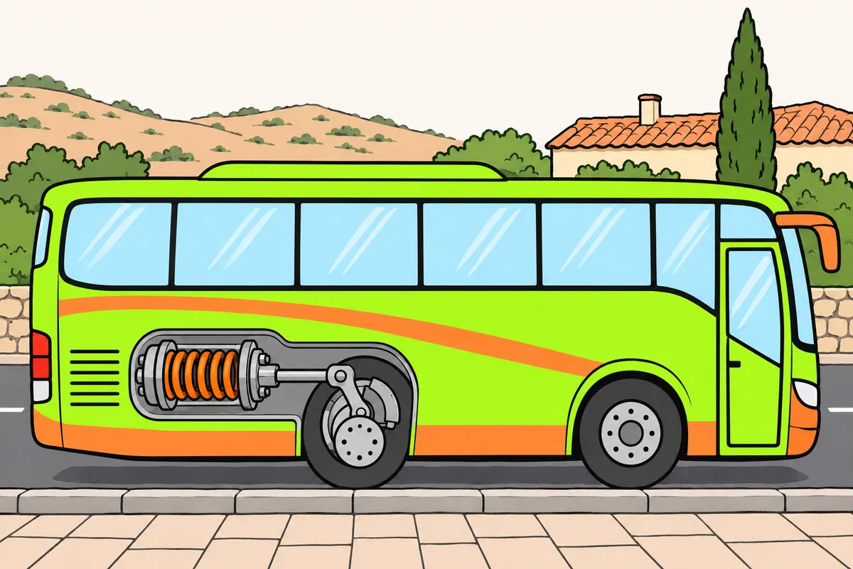
In a spring brake, the spring applies braking and air keeps it released.
| System | Air pressure effect you should remember |
|---|---|
| Air-operated service brake | Pressure applies braking |
| Spring brake chamber | Pressure keeps the brake released |
Remember
- When you apply the parking brake, air escapes and the spring applies braking.
- A major pressure loss can apply the spring brakes.
- Stop in response to warnings; do not wait until the air runs out.
- Do not open the chamber or handle the spring, even without air.
- Mechanical release requires specialist assistance and securing the vehicle.
- Do not drive with the spring disabled to bypass a fault.
Exam trap: Wrong: you think air applies the spring parking brake. Right: the spring applies it; air releases it.
Read the full explanation
- In a spring brake chamber, the spring applies the brake and air keeps it released by compressing the spring. By contrast, in the pneumatic service-brake section, you send in pressure to apply the service brakes.
- When you apply the parking brake on this system, air is released from the relevant chamber and the spring applies the brake. Immobilisation does not depend on maintaining continuous air pressure to produce the parking force; it depends on the mechanical force of the spring.
- A significant loss of pressure can cause the spring brakes to apply. The force applied depends on the system’s design and condition; this safety function can cause abrupt braking. Deal with pressure warnings as explained in “Pressure gauges and low-pressure warning”.
- You must not open a spring brake chamber or work on its spring. It can store dangerous energy even without pneumatic pressure. Mechanical release, where available, is part of the specialist recovery procedure and requires you to secure the vehicle against movement.
- You must not drive with the spring brake disabled to avoid dealing with a fault. If it is mechanically released for an intervention, you cannot assume that the parking-brake function it provided is available; follow the technical assistance measures and limitations.
13Hydraulic control and bleed valve
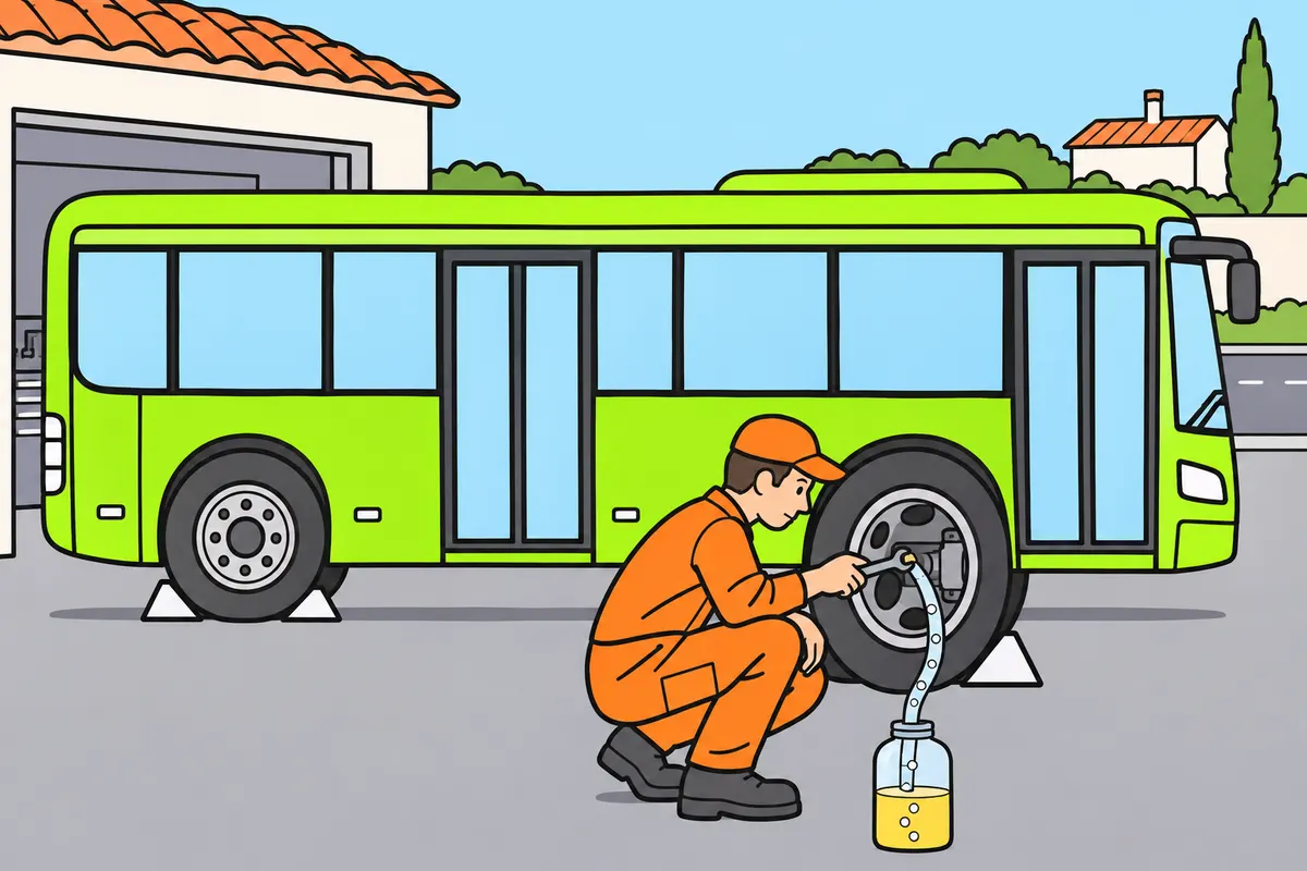
In a hydraulic circuit, you transmit pressure through liquid and must avoid air bubbles.
Remember
- Identify the circuit described: your bus may combine technologies.
- Air bubbles compress and make pressure harder to transmit.
- The bleed valve removes them through a workshop procedure.
- Use the specified fluid; do not mix products because they look similar.
- Topping up the reservoir does not repair a leak.
- If a fault occurs, follow the affected system’s procedure.
Exam trap: Wrong: you mix fluids because both look like oil. Right: use only the fluid specified for that circuit.
Read the full explanation
- In a hydraulic circuit, the pedal generates pressure that the fluid transmits to the brakes; some buses combine technologies.
- Air bubbles are compressible and impair the transmission of hydraulic pressure. The bleed valve allows them to be removed using the workshop procedure.
- Use the specified fluid and follow the manufacturer's checking conditions if your vehicle has this circuit. Topping up a reservoir does not repair a leak, and mixing products because they look alike or because both are called oil can damage the system.
- If there is a hydraulic failure, follow the manufacturer's emergency procedure for that circuit.
14ABS and wheel lock-up
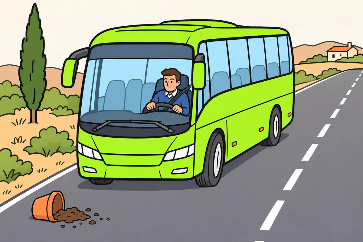
With working ABS, maintain emergency braking and steer your bus with control.
| M3 buses over 12,000 kg | ABS requirement |
|---|---|
| Class I | Exempt |
| Other classes | Compulsory |
Remember
- ABS regulates pressure to prevent wheel locking.
- It helps you steer within the available grip.
- In an emergency, press firmly and maintain the necessary pressure.
- Do not release or pump because of normal pulsations.
- Do not expect to stop in a shorter distance every time.
- If an ABS warning stays on, follow the manufacturer’s instructions.
Exam trap: Wrong: you release the pedal when ABS works in an emergency. Right: with working ABS, maintain the necessary pressure.
Read the full explanation
- ABS detects a tendency for the wheels to lock using information about their rotation and regulates braking pressure. This helps you retain steering control during heavy braking, within the available grip.
- In an emergency with ABS operational, you must press the brake firmly and maintain the necessary pressure while steering the bus towards a safe path, without pumping or releasing the pedal because of the system's normal pulsations. [DGT, emergency braking](https://revista.dgt.es/es/educacion-formacion/conducir-mejor/2023/0315-Frenadas.shtml).
- The feel of the pedal and any pulsations you can feel depend on the system fitted to your bus.
- ABS does not guarantee that you will always stop in a shorter distance or prevent every accident. On loose surfaces, the stopping distance may be greater than with a locked wheel, although retaining steering control can be crucial; adapt your driving and do not treat electronic assistance as an allowance to drive faster.
- If the ABS fault warning remains lit, check what it means and act according to the manufacturer's instructions. Basic braking may remain available without the anti-lock function, but do not assume that every warning means you can continue or that it indicates a complete loss of brakes.
- ABS is compulsory on category M3 buses weighing more than 12,000 kg, except class I buses. [RGV, Annex VIII, section 2, table and note (1)](https://www.boe.es/buscar/act.php?id=BOE-A-1999-1826#anviii).
15EBS and electronic coordination
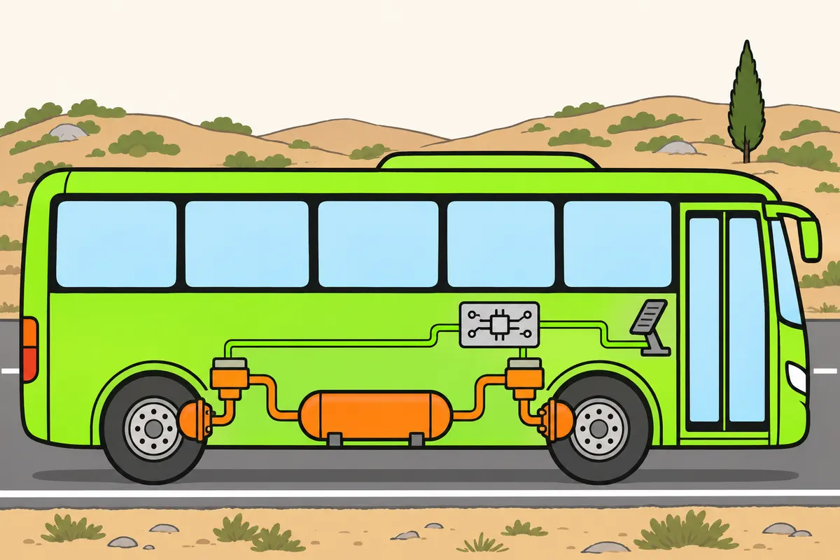
With EBS, you control braking electronically, but still need air in an electro-pneumatic system.
| System | Help you should distinguish |
|---|---|
| ABS | Prevents wheel locking when braking |
| ASR | Limits wheelspin when accelerating |
| ESP | Helps maintain stability |
| EBS | Controls braking electronically |
Remember
- In an electro-pneumatic system, electronics send commands and air supplies energy.
- Check reserves, lines and chambers with EBS too.
- The load-sensing valve adjusts rear brake pressure to load, even without EBS.
- If auxiliary braking is integrated, understand its coordination before using the controls.
- Respect temperature, pressure and grip limits.
- Report faults and follow the diagnostic procedure.
Exam trap: Wrong: you think EBS removes the need for air. Right: in an electro-pneumatic system, air supplies the energy.
Read the full explanation
- EBS controls braking electronically and allows the response to the pedal to be coordinated with less delay than with a conventional pneumatic control.
- In an electropneumatic system, the command is transmitted electronically and air provides the energy. Check the reservoirs, pipes and chambers with EBS too.
- In a conventional pneumatic system, the load-sensing brake correction or regulating valve adjusts the pressure sent to the rear axle brakes to the load it carries. You may find this adjustment without EBS; keep it correctly adjusted and report any fault. The ITV (vehicle roadworthiness test) checks the load-sensing valve. [RD 920/2017, Annex I, section 1.1.17](https://www.boe.es/buscar/act.php?id=BOE-A-2017-12841#ani).
- ABS regulates wheel lock-up when braking; ASR limits wheelspin when accelerating; ESP helps maintain stability; EBS controls braking electronically. Identify each system's warning and check what it means in the bus manual.
- Depending on the equipment, the system may coordinate the service brakes and auxiliary retarder. Check how they are integrated before selecting controls or levels: a control unit distributing the demand does not remove the temperature, pressure or grip limits of each device.
- Report EBS faults and follow the diagnostic procedure. The ITV checks its warnings and indicated faults. [RD 920/2017, Annex I, section 1.7](https://www.boe.es/buscar/act.php?id=BOE-A-2017-12841#ani).
16What retarders are for
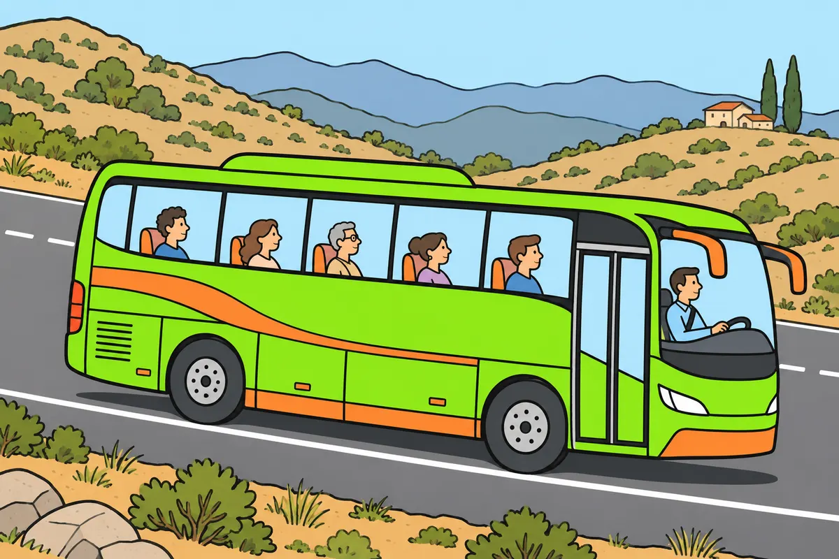
Use your retarder to control speed and reduce work for the service brakes.
Remember
- You reduce brake heating, especially on long descents.
- You can use it in other situations allowed by the manufacturer.
- Increase retardation gradually to avoid jolts.
- Use the intended brakes to complete your stop.
- Use the appropriate brake to keep your bus stationary.
Exam trap: Wrong: you use the retarder instead of the parking brake. Right: the retarder supplements service braking; use the parking brake to hold the bus.
Read the full explanation
- Auxiliary braking limits the increase in speed and reduces heating of the service brakes, especially on long descents. You may also use it in other situations allowed by the manufacturer.
- The retarder supplements the service brake. To complete a stop and keep the bus stationary, you must use the brakes designed for those functions.
- Select the intensity progressively: sudden retardation can unbalance passengers, especially if they are standing.
17Engine braking and exhaust brake
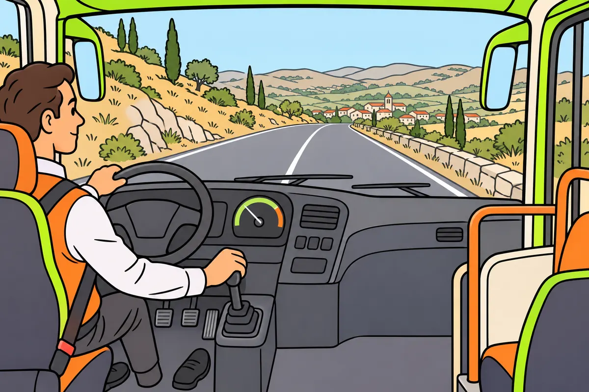
Descend in a suitable gear with the transmission connected to use engine braking.
Remember
- When you release the accelerator, engine resistance helps if the transmission stays connected.
- A low gear gives more engine braking; engine speed limits downshifting.
- Keep your engine running during the descent.
- Do not descend in neutral or with the clutch pressed.
- The exhaust brake restricts the flow of exhaust gases.
- Check your rev counter and maker’s instructions for the right engine-braking speed.
Exam trap: Wrong: you descend with the clutch pressed. Right: keep the transmission connected to retain engine braking.
Read the full explanation
- When you release the accelerator with a gear engaged and the transmission connected, you use the engine's resistance. A low gear gives more engine braking than an excessively high one; the permitted engine speed limits how far you can shift down.
- Keep the engine running and the transmission connected during the descent to make use of this braking effect.
- The exhaust brake restricts the flow of exhaust gases and increases the engine's resistance. Other engine brakes act on the valve timing or compression; their effective speed range and activation depend on the coach's equipment.
- The useful engine-braking speed range depends on the model and may differ from the range used for power when accelerating; check the rev counter and the manufacturer's instructions to identify it.
18Hydraulic retarder
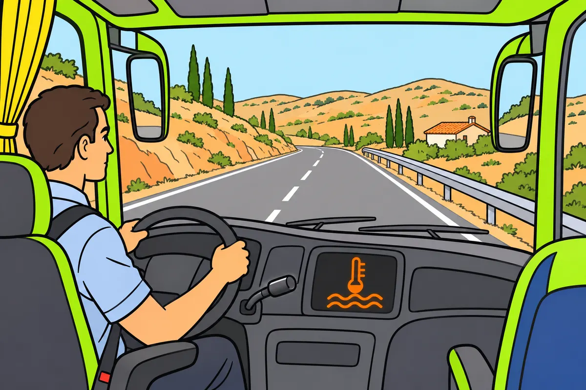
With a hydraulic retarder, you use fluid resistance to slow your bus.
Remember
- Recognise the rotating rotor and fixed stator.
- Fluid between them resists rotation.
- Its effectiveness depends on the speed of the connected component.
- Changing gear may affect it differently from engine braking.
- Watch temperature: protection can reduce retardation.
- Use the fluid specified for your retarder.
Exam trap: Wrong: you confuse its fluid with hydraulic wheel brake fluid. Right: these are different systems; follow their specific maintenance requirements.
Read the full explanation
- In a hydraulic or hydrodynamic retarder, a rotor turns opposite a fixed stator. The movement of fluid between them generates resisting torque.
- The unit may be integrated into the gearbox or transmission. Its effectiveness depends on the rotational speed of the component to which it is connected; changing gear may have a different effect from doing so with the engine brake.
- The absorbed energy is converted into heat and carried away by the designated cooling circuit. Watch the temperature warnings: thermal protection may reduce the available braking effect.
- Use the specified fluid for the retarder; its operation and maintenance differ from those of a hydraulic wheel-brake circuit.
19Electric retarder
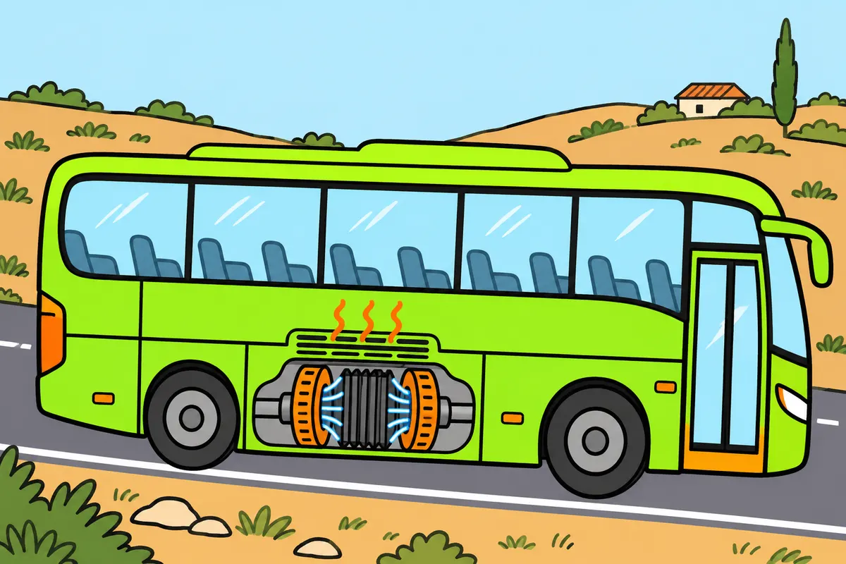
With an electromagnetic retarder, you slow the bus using magnetic forces without frictional contact.
| Device | Where the energy goes |
|---|---|
| Electromagnetic retarder | Releases energy as heat |
| Electric bus regenerative braking | Recovers some energy for storage |
Remember
- The magnetic field creates currents that oppose rotation.
- You still produce heat without frictional contact.
- Follow cooling, use and maintenance requirements.
- Identify the device fitted to your bus.
Exam trap: Wrong: you think no friction means no heat or maintenance. Right: this retarder produces heat and needs care.
Read the full explanation
- In an eddy-current electromagnetic retarder, the stator creates a magnetic field that induces currents in the rotors and opposes their rotation without frictional contact.
- The absorbed energy is dissipated as heat. Follow the equipment's cooling, use and maintenance requirements.
- This retarder dissipates energy; a regenerative braking system in an electric bus recovers some of it for storage. Identify the device installed in your vehicle.
20Grip and auxiliary braking
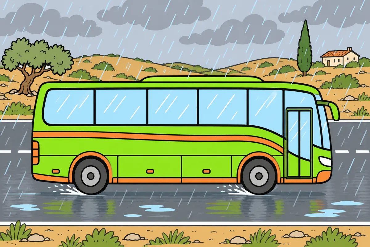
On slippery surfaces, adapt auxiliary braking to grip and follow the manufacturer’s instructions.
Remember
- Hydraulic and electromagnetic transmission retarders brake your driven wheels.
- On slippery surfaces, that axle can lose grip.
- Follow the manufacturer’s restrictions.
- If use is allowed in these conditions, select stages smoothly.
- Adapt retardation to the surface, axle load and speed.
- Check coordination with ABS and EBS; avoid destabilising your bus, especially on bends.
Exam trap: Wrong: you use the retarder on ice, trusting electronics. Right: follow the manufacturer’s restrictions and adapt retardation to grip.
Read the full explanation
- Hydraulic and electromagnetic retarders connected to the transmission hold back the driven wheels. On a slippery surface, they can cause that axle to lose grip.
- Follow the manufacturer's restrictions: if the manufacturer permits use of the retarder in those conditions, select its stages smoothly and adapt the braking effort to the surface, axle load and speed.
- How the retarder works with ABS and EBS depends on the equipment. Check its operation in the manual and avoid applications that could destabilise the bus, especially on bends.
21Brake fade and reduced effectiveness
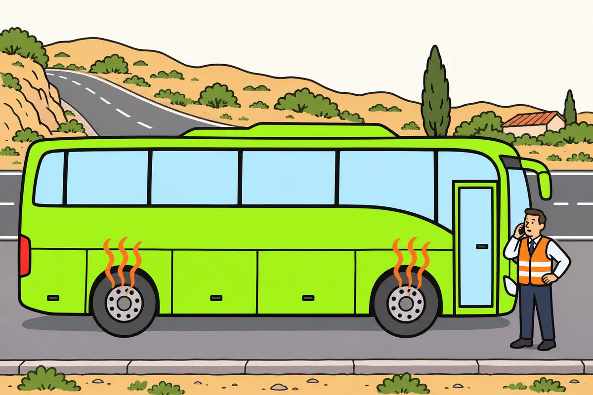
You can lose braking effectiveness by overheating your service brakes on descents.
| Overheating case | What you should remember |
|---|---|
| Overheated wheel brakes | You can lose braking effectiveness through excessive heat |
| Overheated fluid in a hydraulic circuit | Vapour can impair pressure transmission; report a loss of response. |
Remember
- Brake fade means reduced braking effectiveness caused by excessive heat.
- Pressing harder does not remove accumulated heat.
- Choose speed, gear and auxiliary braking before your brakes overheat.
- With more weight, you must manage more energy during the descent.
- If braking weakens, smells strongly or triggers temperature warnings, stop safely and seek assistance.
- Follow the cooling procedure; do not pour water onto hot components.
Exam trap: Wrong: you continue because the smell fades. Right: follow the manufacturer’s cooling and inspection procedure before continuing.
Read the full explanation
- Brake fade is the loss of braking effectiveness due to excessive heat, especially in friction materials. If you rely too heavily on the service brakes on a descent, pressing the pedal harder does not remove the accumulated heat.
- The weight of passengers and luggage increases the energy you have to manage on the descent. Heating also depends on how long braking is demanded and on the cooling available: a speed that seems stable may require sustained thermal effort.
- If you notice reduced effectiveness, a strong smell or a temperature warning, find a safe place to stop and get assistance. Follow the manufacturer's cooling and inspection procedure before continuing; the smell fading does not confirm that the system is fit for service. Avoid pouring water over hot components to speed up cooling.
- In a hydraulic circuit, excessive fluid heating can produce vapour and impair pressure transmission. Report this loss of response so that the circuit and fluid condition can be checked against the manufacturer's specifications.
22Prolonged descents
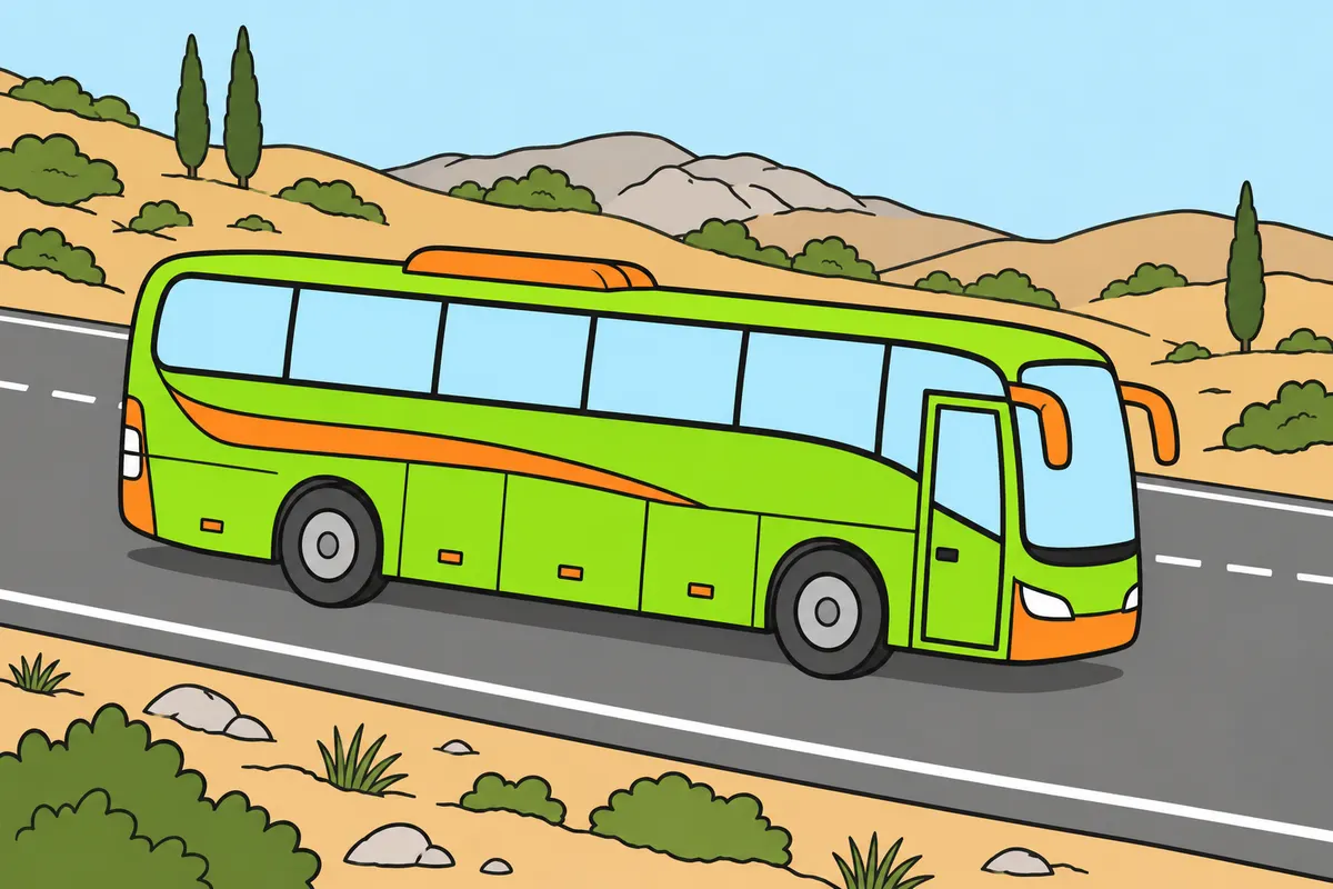
Prepare for descents and combine gears, auxiliary braking and service braking to control speed.
Remember
- Reduce speed and choose a suitable gear before descending.
- Adapt auxiliary braking to gradient, load, bends and equipment.
- Watch engine speed and temperatures.
- When using service braking, reduce speed effectively and release it when conditions allow.
- Avoid continuous light braking; seek a safe stop for alarms or continuous braking.
- For serious failure, follow the manual; use an accessible, suitable escape area.
Exam trap: Wrong: you brake lightly throughout the descent. Right: reduce speed and release the service brake when conditions allow.
Read the full explanation
- Before the descent, reduce speed and select the appropriate transmission ratio. Do not wait until the bus gathers speed before selecting a low gear; prepare to hold it back in good time, taking account of the gradient, load, bends and the coach's equipment.
- During the descent, aim to use a combination of gear and auxiliary braking that keeps your speed under control. Monitor engine speed and temperatures; if the available braking effort is insufficient, reduce speed using the service brakes and adjust your approach when you can do so safely.
- When you need the service brakes, apply them in a controlled way that effectively reduces speed, then release them when conditions allow. Avoid keeping them lightly applied continuously; adapt your technique to the gradient and vehicle.
- Adapt your braking to bends and passengers, without mistaking smoothness for allowing your speed to increase. If you need to keep applying the service brakes or a warning appears, your approach may exceed the vehicle's capacity: find a safe place to stop and assess the situation.
- If a serious failure occurs, use the emergency measures in accordance with the manual, maintain your course and use an escape area when it is accessible and suitable. Passenger protection and assistance are covered in “Passenger safety and emergencies”.
23Accelerator and braking management
Accelerate smoothly and learn how your bus coordinates the accelerator and auxiliary braking.
| Driving aid | What you should know |
|---|---|
| Cruise control | Acts on the engine to maintain your chosen speed |
| Speed limiter | Limits power; you must manage braking on descents |
Remember
- Your electronic pedal sends your demand to the engine control unit.
- Accelerate gradually to avoid jolts.
- Know how to turn off cruise control.
- Check when auxiliary braking activates and deactivates.
- If the accelerator sticks, press the clutch or select neutral following your gearbox procedure.
- Brake, stop safely and seek assistance; do not bend down to touch the pedal.
Exam trap: Wrong: you rely only on the speed limiter during a descent. Right: you must also manage braking.
Read the full explanation
- In a bus with an electronic accelerator, pedal sensors send your demand to the engine control unit, which regulates torque delivery and, in a diesel engine, fuel injection. Accelerate progressively to avoid jolting passengers.
- Cruise control acts on the engine to maintain the selected speed; you must know how to suspend it using its controls and by braking. The speed limiter restricts power delivery when it reaches its setting: on a descent, you also need to manage the braking effort. The limits and required equipment are covered in “Bus dimensions and masses”.
- In an exhaust brake, the butterfly valve control works in coordination with fuel injection cut-off. In integrated systems, electronic management coordinates auxiliary braking with accelerator demand; check the conditions for activating and disengaging it in your coach. [DGT, Manual VIII, 2025 edition, section 4.2](https://sede.dgt.gob.es/export/sites/dgt/.galleries/permisos-de-conducir/certificacion-aptitud-profesores-formacion-vial/2025/Manual-VIII-Mecanica-2025.pdf).
- If the accelerator sticks and continues to drive the bus forward, press the clutch if there is one, or select neutral in accordance with the transmission's emergency procedure, brake and stop in a safe place. Keep control of the steering and request assistance; do not bend down to handle the pedal while moving.
24Trailer and coupling lines
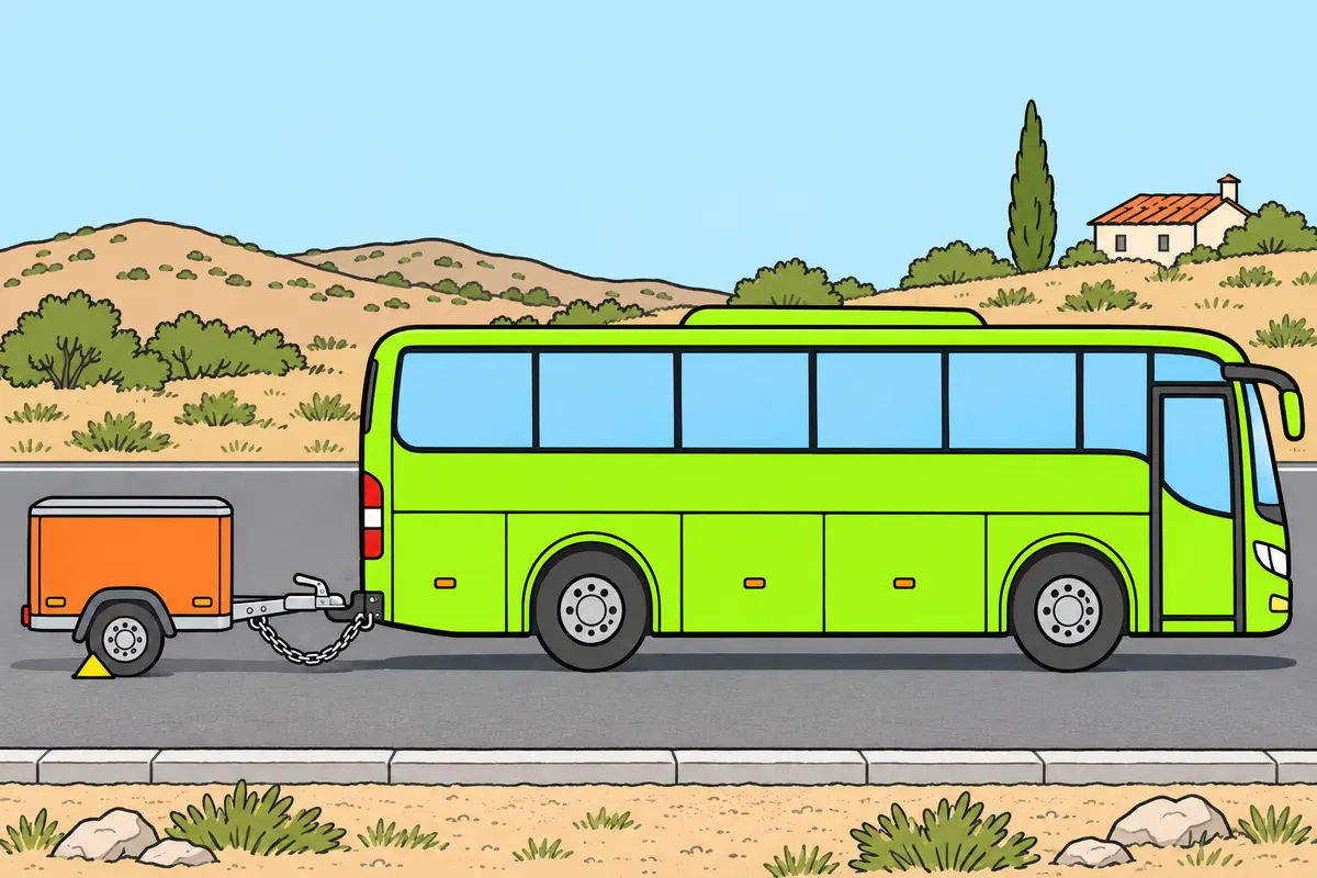
Check your licence, coupling and equipment before towing a trailer.
| Trailer case | What you should distinguish |
|---|---|
| Above 750 kg maximum authorised mass | You need D+E |
| Separation or coupling failure while moving | Automatic braking stops the trailer without impairing braking of the rest of the combination |
Remember
- With D, also respect the authorised capacity of your bus and coupling.
- A trailer up to 750 kg maximum authorised mass may have no brakes.
- Up to 1,500 kg maximum authorised mass, without breakaway braking, use a secondary coupling.
- It must prevent the drawbar touching the ground and keep some trailer guidance.
- Check the trailer’s equipment and your bus’s coupling requirements.
Exam trap: Wrong: you think a light trailer without brakes needs no secondary coupling. Right: up to 1,500 kg maximum authorised mass, use one if there is no braking on coupling failure.
Read the full explanation
- With a category D licence, you may tow a trailer with an MMA of up to 750 kg, within the authorised capacity of the bus and coupling device. [RGCond, art. 4.2](https://www.boe.es/buscar/act.php?id=BOE-A-2009-9481#a4).
- A trailer with an MMA of up to 750 kg may have no brakes of its own. Check its equipment and comply with the bus's coupling requirements. [RGV, Annex VIII, section 2, category O1](https://www.boe.es/buscar/act.php?id=BOE-A-1999-1826#anviii).
- If the trailer has an MMA of up to 1,500 kg and has no braking system that operates if the coupling breaks, you must use a secondary coupling, such as a chain or cable, to prevent the drawbar from touching the ground and retain some control of the trailer. This includes an unbraked light trailer. [RGV, art. 13.4](https://www.boe.es/buscar/act.php?id=BOE-A-1999-1826#a13).
- A trailer over 750 kg requires category D+E; the limits on towable mass with an overrun brake or without brakes are covered in “Bus dimensions and masses”. [RGCond, art. 4.2](https://www.boe.es/buscar/act.php?id=BOE-A-2009-9481#a4); [RGV, Annex IX, section 4.1.2](https://www.boe.es/buscar/act.php?id=BOE-A-1999-1826#anix).
- The automatic braking system stops the trailer if it separates or the coupling breaks while moving, without reducing the braking effectiveness of the rest of the combination. [RGV, art. 12.8.3 and Annex VIII, section 1.5](https://www.boe.es/buscar/act.php?id=BOE-A-1999-1826#anviii).
25Checks and the decision to set off
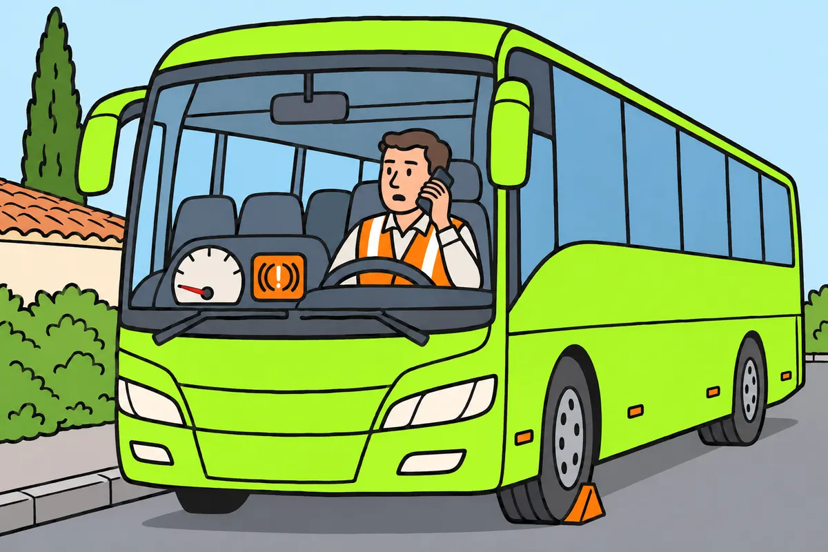
Do not depart with passengers if your brakes have a fault.
Remember
- Check air charging, readings and warnings for your model.
- With your bus secured, check persistent leaks, lines and controls within the authorised inspection.
- Do not go underneath if only air suspension supports your bus.
- Do not loosen pressurised connections to find leaks.
- Test brake response slowly in a suitable area, following the procedure.
- Cancel departure and report insufficient pressure, pulling, serious warnings or abnormal response.
Exam trap: Wrong: you compensate for a fault by driving more slowly with passengers. Right: cancel departure; you must be able to brake from the start.
Read the full explanation
- Before starting the service, you must check that the system builds up air pressure, that the readings are consistent and that the warning systems perform the expected checks. Refer to the vehicle model to see which warning lights go out as pressure builds up or when you start moving; do not guess what they mean based on colour alone.
- With the bus secured, you must check for persistent leaks, damaged pipes and correct operation of the controls as part of the authorised inspection. Never go under a vehicle supported only by air suspension or loosen a pressurised connection to look for a leak.
- Check the brake response at low speed in a suitable place and in accordance with the departure procedure. Make sure the response is normal and controlled; a brief test does not replace a pending repair or guarantee thermal performance on a prolonged descent.
- If you find a serious braking fault, you must suspend departure and report it for repair. The bus must be able to stop from the start of a journey carrying passengers. This decision protects passengers and fulfils your duty to drive without endangering the occupants. [RGC, art. 3.1](https://www.boe.es/buscar/act.php?id=BOE-A-2003-23514#a3).
- Follow the manufacturer's maintenance schedule for the brakes, air dryer and retarders, and record faults in accordance with the service's procedures. Details of the maintenance plan and inspections are covered in “Bus maintenance and checks”. The link between the failed component and the loss of braking effectiveness helps you assess how serious the fault is.
Check the pneumatic circuit before setting off
Follow this general sequence together with the values and tests specified by the bus manufacturer.
- Secure the vehicle against movement and check that you can see the indicators without creating a hazard.
- Switch on and operate the system as described in the manual; check the warning lamps and audible warning test.
- Wait for the circuits to charge and check all pressure readings and that the warnings go out, as specified for the model.
- Check for leaks and test the controls using the approved checks. Do not dismantle pressurised components or use air unnecessarily.
- Carry out a low-speed response test in a suitable place. If you find any irregularities, do not set off and request an inspection.
Prepare for and manage a long descent
Maintain braking effectiveness by sharing the work between the selected gear and the available retarding systems.
- Assess the gradient, bends, load, grip and retarding capacity before starting the descent.
- Reduce speed and select a suitable gear without exceeding the engine’s permitted speed range.
- Select the auxiliary retarder permitted by the manufacturer and apply it progressively.
- Monitor speed, engine speed, pressure and temperature; use the service brake when necessary to regain a controlled speed.
- If you need to brake continuously or braking effectiveness falls, look for a safe place to stop and assess the situation.
Emergency braking with ABS operating
Apply the braking force needed and let the anti-lock system regulate it.
- Press the brake pedal firmly when faced with danger and keep control of the steering wheel.
- Maintain the necessary pressure without pumping or releasing the pedal because of the normal ABS pulsations.
- Steer the bus along a safe path permitted by the available grip and avoid unnecessary sudden movements.
- Complete the stop and secure the vehicle. If there is a fault, follow the inspection and assistance procedure.
Respond to a serious brake warning
Do not wait until you have lost all braking capacity before taking action.
- Identify the warning without becoming distracted and check whether it concerns pressure, temperature or an electronic fault.
- Reduce the risk, maintain your course and look for a safe place to stop, using the available means in accordance with the manual.
- Avoid pumping a pneumatic circuit and do not apply the parking brake abruptly as a general response.
- Once stopped, secure the bus, protect the passengers and request an inspection or assistance.
- Do not resume service until the cause affecting safety has been resolved; the warning going out by itself does not prove that the fault has been repaired.
Finished this module?
Mark it as read and you will see your progress on the theory list.