
Theory · D Licence - Bus · Module 15 of 18
Bus mechanics
You learn about the bus's diesel engine, fuel supply, lubrication, cooling, starting system and electrical system, as well as its transmission, suspension, steering, and tyre construction and markings. Checks are covered in «Bus maintenance and checks» and braking in «Bus brakes and retarders».
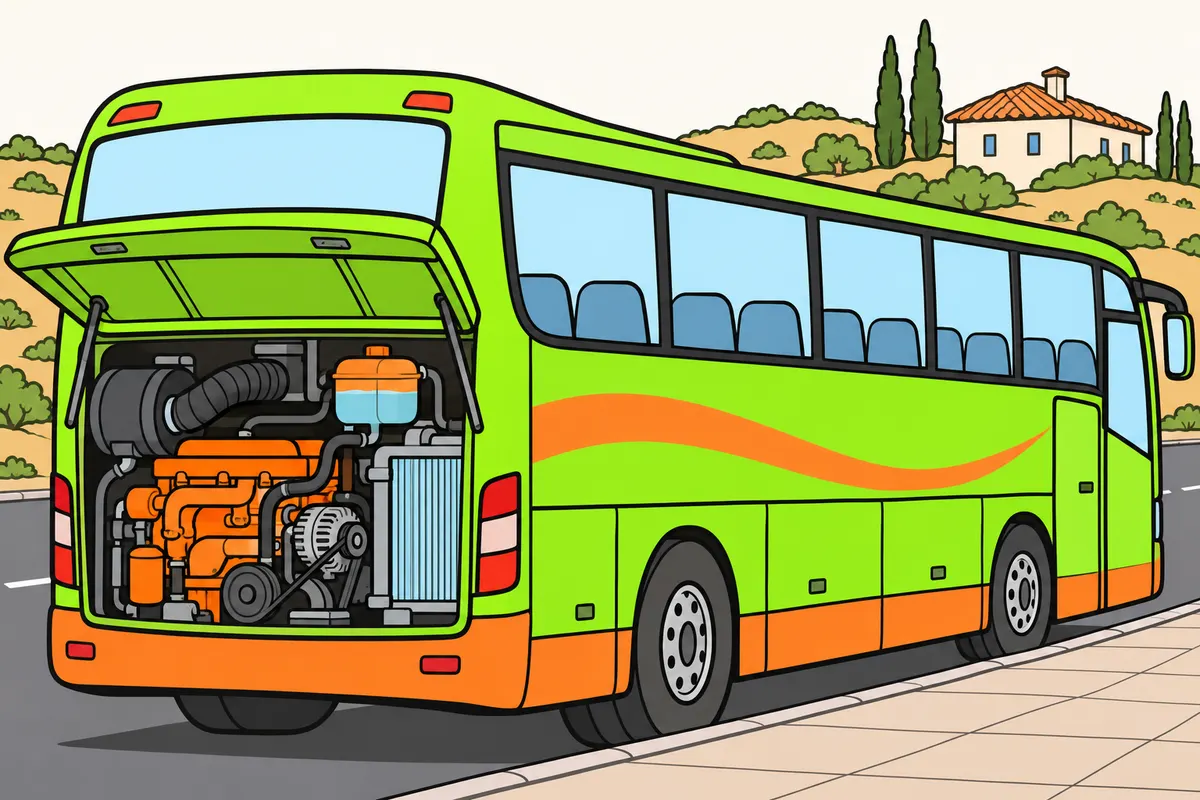
1Bus systems and scope of the module
You learn how the bus's mechanical systems work.
Remember
- Study how the engine and its systems work here.
- Find checks and breakdown advice in «Bus maintenance and checks».
- Study braking systems in «Bus brakes and retarders».
- Find retarder use on descents in «Safe bus driving».
Exam trap: Wrong: you look for checks here. Right: study them in «Bus maintenance and checks».
Read the full explanation
- In your bus, the engine provides power, the transmission delivers it to the driven wheels, and the steering and suspension allow you to guide the vehicle and keep its wheels in contact with the road surface.
- Servicing, fluid levels, wheels, lighting, windscreen wipers and how to respond to breakdowns are covered in «Bus maintenance and checks».
- Brake circuits, ABS, EBS and retarders are covered in «Bus brakes and retarders»; their use on descents is covered in «Safe bus driving».
2Combustion, valve timing and the flywheel
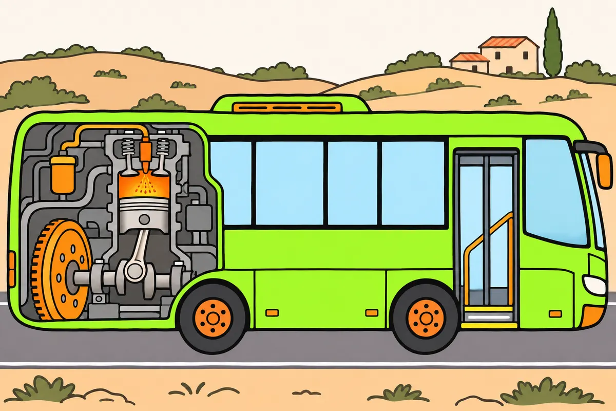
In a diesel engine, fuel ignites when it mixes with very hot compressed air.
| System | Function |
|---|---|
| Valve timing | Controls gases entering and leaving by opening and closing valves |
| Fuel and air supply | Supplies air and fuel |
| Transmission | Carries motion to the wheels |
Remember
- Remember: the piston compresses air and raises its temperature.
- You do not need a spark plug's spark in each diesel cycle.
- With direct injection, remember that fuel mixes with air inside the cylinder.
- You can find direct injection in both diesel and petrol engines.
- Find the flywheel at one end of the crankshaft.
- Remember: it stores rotational energy and smooths changes in engine speed.
Exam trap: Wrong: the flywheel always keeps engine speed exactly constant. Right: it smooths speed changes.
Read the full explanation
- In a conventional compression-ignition diesel engine, the piston compresses air and greatly increases its temperature. The system injects fuel when this air is compressed and very hot: the fuel mixes with it and ignites spontaneously under the appropriate operating conditions.
- The four-stroke cycle consists of air intake, compression, combustion and expansion, and exhaust. Expansion pushes the piston and turns the crankshaft through the connecting rod.
- With direct injection, fuel is injected and mixes with air inside the cylinder, in the combustion chamber. Both diesel and petrol engines can use direct injection; injection timing depends on the design.
- Identify the valve timing system as the system that controls gases entering and leaving the cylinders by opening and closing valves. The fuel and air supply system supplies air and fuel; the transmission transfers motion to the wheels.
- The flywheel, located at one end of the crankshaft, stores rotational energy to keep it turning between the engine's power impulses and carry the pistons past their dead centres. It smooths out variations in speed.
3Diesel fuel supply: distinguish pumps from injectors
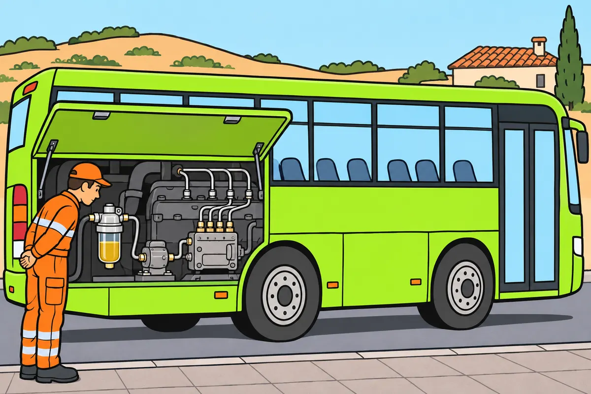
Distinguish the pumps that move and pressurise diesel from the injectors that deliver it.
| Part, where fitted | Function |
|---|---|
| Feed pump, with separate pumps | Carries diesel through the low-pressure circuit |
| High-pressure pump | Brings fuel to the required pressure |
| Injectors | Deliver fuel into the cylinders |
Remember
- Use the fuel specified for your bus.
- Remember: filters trap impurities in diesel fuel.
- If fitted, use the water separator to remove water.
- Do not loosen high-pressure pipes to look for leaks.
- With conventional mechanical injection, find the governor in the injection pump.
- Do not assume electronic injection has the same layout.
Exam trap: Wrong: the piston draws diesel fuel directly from the tank. Right: with separate pumps, the feed pump carries it.
Read the full explanation
- In a circuit with separate feed and injection pumps, the feed pump carries diesel from the tank towards the injection system through the low-pressure circuit and its filters.
- The high-pressure pump brings the fuel to the required pressure; the injectors deliver it into the cylinders. Fuel metering and pressure generation depend on the system; designs may combine these components or keep them separate.
- In a conventional mechanical injection pump, the governor is part of the injection pump. It adjusts the fuel supply to limit maximum engine speed and maintain idling. This arrangement does not automatically apply to electronic injection.
- You must use the fuel specified for your bus. Dirt and water in diesel harm the injection system; filters trap impurities and the water separator, where fitted, allows you to remove water. Do not loosen high-pressure pipes to look for leaks.
4Air intake, turbocharger and intercooler
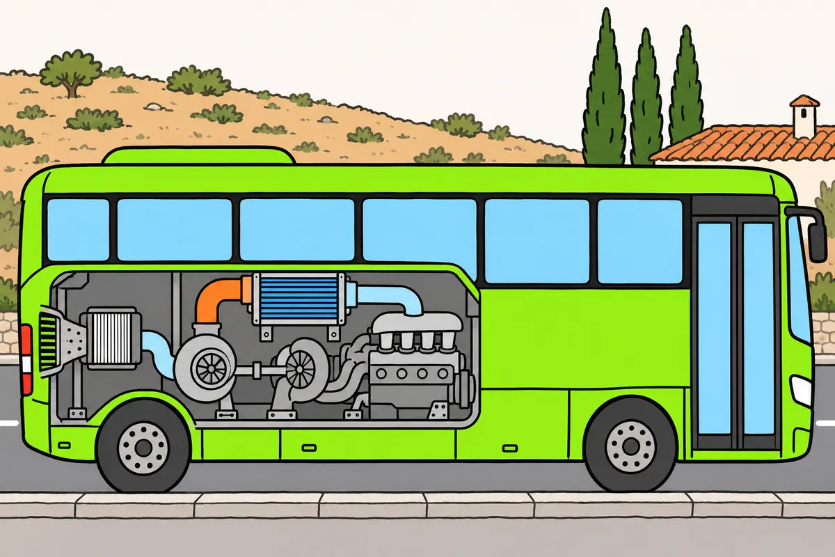
The intercooler cools compressed air before it enters the engine.
Remember
- With a turbocharger and intercooler, follow the air's route.
- Remember: air passes through the filter, then the turbocharger compressor.
- Then follow it through the intercooler and into the cylinders.
- Remember: the filter traps particles; a blocked filter restricts air intake.
- In a conventional turbocharger, remember that oil lubricates bearings and removes heat.
Exam trap: Wrong: the intercooler cools oil. Right: it cools compressed air.
Read the full explanation
- The air filter traps particles in the air entering the engine and protects its components; a blocked filter restricts the air intake.
- In an engine with a turbocharger and intercooler, follow this route: air filter, turbocharger compressor, intercooler and intake into the cylinders. The filter comes before the compressor to protect both it and the engine from particles.
- The intercooler cools air heated by compression in the turbocharger before it enters the engine; this helps fill the cylinders.
- In a conventional turbocharger, engine oil lubricates its bearings and helps remove heat.
5Lubrication: circuit, viscosity and oil selection
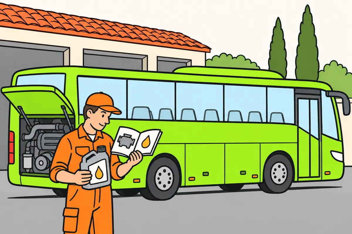
Choose oil by the manufacturer's specifications as well as its viscosity.
| Example oil | Meaning |
|---|---|
| SAE 20W-40 | Multigrade: 20W describes cold performance; 40 is the hot grade. W means winter |
| SAE 20 and SAE 60 | Monograde: the numbers do not indicate temperature or service life |
Remember
- In four-stroke wet-sump engines, find collected oil at the bottom of the engine.
- Remember: the pump pushes oil around; the filter removes solid impurities.
- If a bypass valve is fitted, expect some oil to bypass filtering temporarily.
- Understand viscosity as resistance to flow: it normally falls as oil heats up.
- Check the required performance and approvals, not colour or SAE grade alone.
- If you have a particulate filter, use oil compatible with it.
Exam trap: Wrong: SAE 20W-40 gives temperatures. Right: it gives viscosity grades, not temperatures.
Read the full explanation
- In a four-stroke engine with a wet sump, the sump closes off and protects the bottom of the engine block and collects the oil returning after lubricating the components. The drain plug is at its bottom.
- The oil filter separates out solid impurities, such as debris and wear particles, to protect the components. If a bypass valve is fitted, it may temporarily allow unfiltered oil through to maintain the supply.
- The pump delivers oil to the lubrication points. The lubricating film reduces friction and wear, helps remove heat and carries impurities towards the filter.
- Viscosity expresses the oil's resistance to flow and normally decreases as it heats up. You must distinguish it from quantity, pressure and temperature.
- SAE 20W-40 is a multigrade oil: 20W expresses its viscosity performance at low temperatures and 40 its high-temperature grade. W means winter. SAE 20 and SAE 60 are monograde oils; their numbers do not indicate degrees of temperature or how many kilometres they last. [DGT, Manual VIII, topic 5](https://sede.dgt.gob.es/.galleries/permisos-de-conducir/certificacion-aptitud-profesores-formacion-vial/2023/Manual-VIII-Mecanica-2023.pdf).
- You must select both the viscosity grade and the performance specifications and approvals required by the bus manufacturer. Two containers with the same SAE grade may meet different needs; you cannot choose by the oil's colour either. If your bus has a particulate filter, you must also ensure that the lubricant is compatible with the exhaust gas treatment system.
6Oil pressure: instruments and their meaning
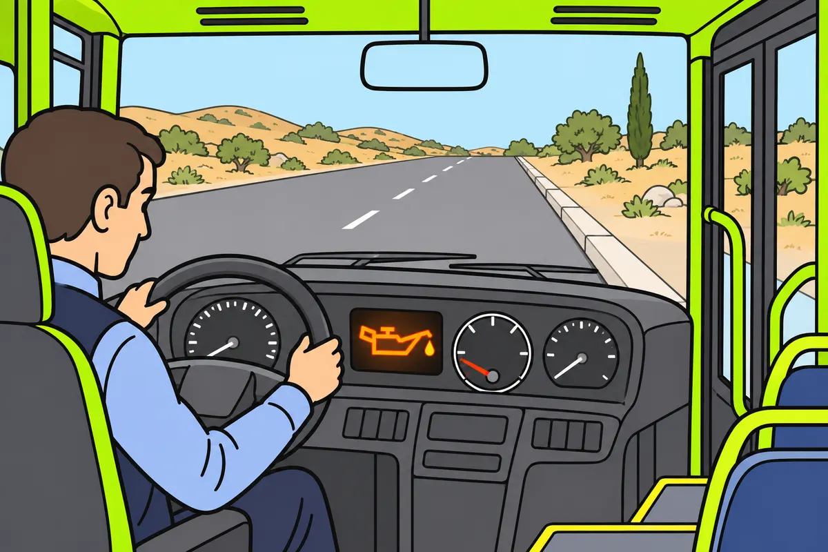
A correct oil level does not guarantee enough oil pressure.
| Instrument | Function |
|---|---|
| Pressure gauge | Shows the oil pressure reading |
| Oil pressure switch | Can activate a low-pressure warning light |
| Temperature gauge | Measures temperature |
Remember
- The pressure gauge shows pressure; the switch can activate a low-pressure warning light.
- Do not identify the cause from the warning light alone.
- Consider low oil, unsuitable viscosity, excessive heat or circuit faults as possible causes.
- Check «Bus maintenance and checks» for how to respond.
- Do not expect every vehicle to have an oil pressure gauge.
Exam trap: Wrong: a correct oil level rules out pressure problems. Right: the circuit may still fail to supply oil properly.
Read the full explanation
- The pressure gauge shows you the oil pressure reading. The oil pressure switch is a pressure-sensitive switch that can activate a low-pressure warning light; it does not provide the same reading. The temperature gauge measures temperature. Not all vehicles have an oil pressure gauge.
- With the engine running, the oil pressure warning light can warn you of insufficient pressure; a correct oil level does not guarantee that the pump and circuit are supplying oil properly.
- Low pressure may be due to insufficient oil, unsuitable viscosity, excessive temperature or a fault in the circuit; the warning light alone does not identify the cause. How you respond to the warning is covered in «Bus maintenance and checks».
7Engine cooling
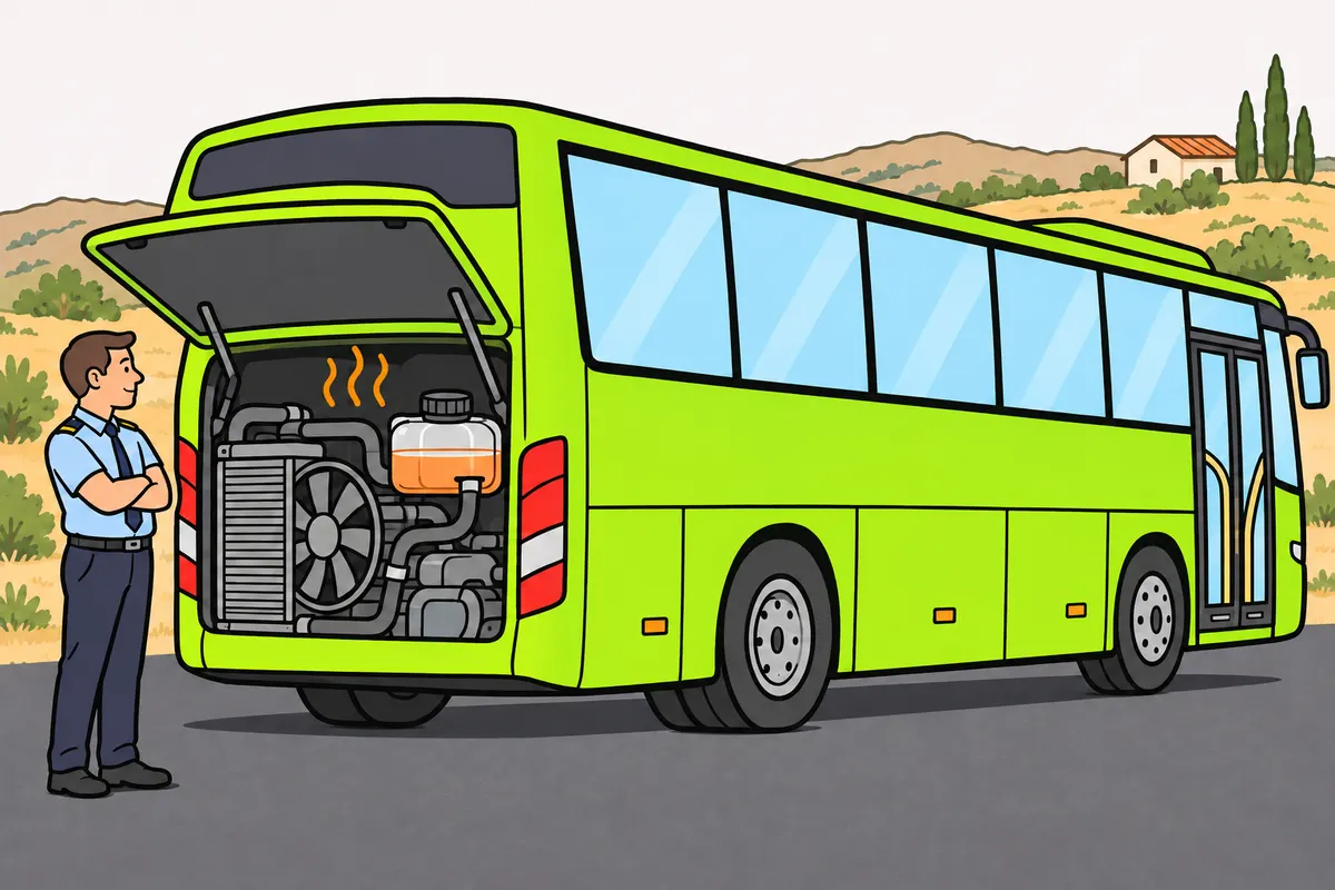
Coolant absorbs engine heat and releases it through the radiator.
| Part | Function |
|---|---|
| Pump | Circulates coolant |
| Radiator | Releases heat to the surroundings |
| Thermostat | Controls flow to the radiator according to temperature |
| Expansion tank | Accommodates changes in coolant volume |
| Cap | Maintains the specified pressure through valves |
Remember
- Do not open a hot, pressurised cooling circuit: you could burn yourself.
- Choose coolant with the specified requirements, composition and concentration.
- Do not choose by colour or mix incompatible products.
- Remember: even a sealed circuit can lose coolant.
- If a belt drives the pump, remember that belt failure can cause overheating.
- Consider low coolant, leaks, thermostat faults and fan faults as other possible causes.
Exam trap: Wrong: a closed circuit needs no fan or antifreeze protection. Right: it still needs both.
Read the full explanation
- The coolant pump forces coolant to circulate between the engine's water jackets and the radiator.
- The coolant absorbs heat from the engine, and the radiator releases it to the outside air to cool the liquid. The thermostat regulates flow to the radiator according to temperature.
- A closed, sealed circuit reduces coolant loss. The fan helps air flow through the radiator when cooling is needed, and antifreeze protection prevents the coolant from freezing at low temperatures.
- The expansion tank accommodates changes in coolant volume. The cap maintains the specified pressure through its valves; you must not open the hot, pressurised circuit because of the risk of burns.
- Choose coolant according to the specified requirements, composition and concentration, and the protection needed against expected temperatures, including those below zero. Colour does not guarantee compatibility; do not mix incompatible products or alter the prescribed ratio.
- If the pump is belt-driven, a broken belt can stop circulation and cause overheating. Low coolant levels, leaks, or thermostat or fan faults can also cause overheating; the pump's drive arrangement depends on the engine.
8Clutch, gearbox and transmission to the wheels
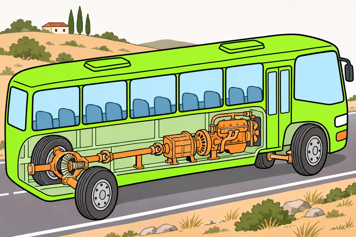
The transmission carries engine motion to the wheels and changes the turning force.
| Part or system, where fitted | Function |
|---|---|
| Gearbox | Lets you select ratios |
| Bevel final drive in a conventional transmission with a propeller shaft | Fixed reduction: less rotational speed and more turning force |
| Differential | Allows different wheel speeds when cornering |
| Propeller shaft universal joints | Transmit rotation through changing angles |
| Hydraulic clutch control | Transmits force through fluid; air or leaks can make disengaging difficult |
| Automatic gearbox with torque converter | Uses a torque converter |
| Automated gearbox | Operates a clutch automatically |
Remember
- With a clutch pedal, press to disconnect; release gradually to reconnect.
- Avoid resting your foot on the pedal or holding the bus uphill by slipping.
- If your loaded bus slows uphill, choose a lower gear without straining the engine.
- Use the specified lubricant: some gearboxes need fluids other than gear oil.
- Do not descend in neutral or rely solely on the gearbox when stationary.
- Do not assume an electric bus has a conventional clutch.
Exam trap: Wrong: universal joints provide fixed reduction. Right: with a conventional propeller shaft and bevel final drive, the final drive provides it.
Read the full explanation
- In a conventional mechanical transmission, you must recognise this power path: engine, clutch, gearbox, propeller shaft, final drive with differential, and half-shafts to the driven wheels. The layout varies according to the position of the engine and the driven axles; an electric bus may use a different arrangement and have no conventional clutch.
- The clutch progressively connects or interrupts the transmission of engine torque to the gearbox. When you disengage the clutch by pressing the pedal, you break this connection; when you release it progressively, you restore the connection. You must not rest your foot continuously on the pedal or hold the bus stationary on a slope by slipping the clutch: you convert energy into heat and accelerate wear.
- The gearbox allows you to select different gear ratios. In a conventional transmission with a propeller shaft and bevel final drive, the drive pinion and crown wheel provide another, fixed reduction ratio: they reduce rotational speed and increase torque; in this arrangement, they also change the direction of rotation.
- The differential allows the wheels to turn at different speeds when cornering. Its planet gears and side gears make this difference in rotational speed possible. The universal joints in the propeller shaft allow it to transmit rotation through varying angles.
- In gearboxes and final drives that require gear oil, this lubricant is commonly called valvulina (gear oil) in Spain. You must use the manufacturer's specified lubricant: some gearboxes use other fluids, and viscosity grade alone does not determine compatibility.
- The hydraulic clutch control transmits force through a fluid from the master cylinder to the slave cylinder. A leak or air entering the system can make it difficult to disengage the clutch; checks and topping up are covered in «Bus maintenance and checks».
- A low gear multiplies torque at the wheels more, at the cost of a lower road speed for the same engine speed. If the laden bus loses engine speed on an uphill slope, select a suitable lower gear without straining the engine. Tractive force must overcome resistance to motion.
- An automatic gearbox with a torque converter transmits force through a fluid; an automated gearbox operates a clutch automatically. They do not all have a clutch pedal or use the same oil. Use the selector positions and procedures in the manual; do not select neutral on a descent or rely solely on the transmission to secure the bus.
9Steering and power assistance
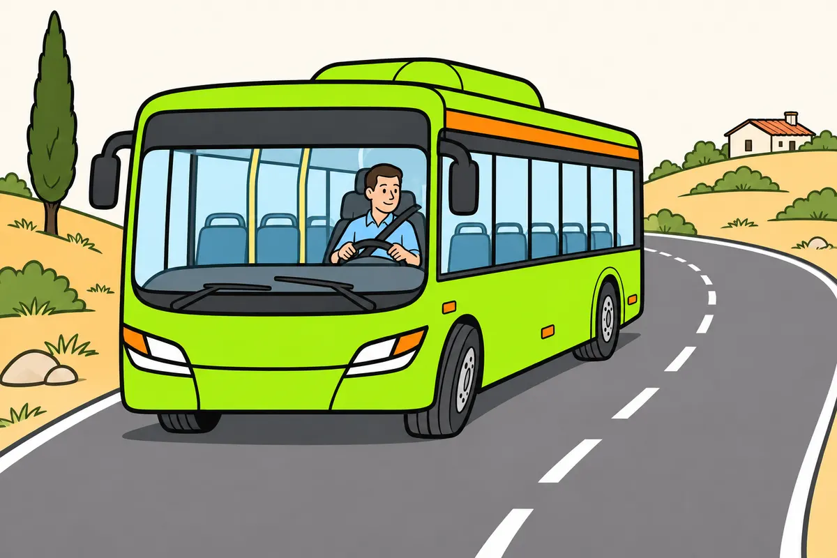
Power steering reduces the effort you need to turn the steering wheel.
| Power steering type | How it helps |
|---|---|
| Hydraulic | A pump supplies pressurised fluid; a valve distributes assistance |
| Electric | Uses an electric motor |
Remember
- Use the steering wheel to change the direction of the steered wheels.
- When cornering, remember that each wheel follows a path with a different radius.
- Identify the type of power steering fitted to your bus.
- If you lose assistance, you need more effort to turn the steering wheel.
Exam trap: Wrong: all power steering has a hydraulic reservoir. Right: electric power steering may have none.
Read the full explanation
- The steering system converts movement of the steering wheel into changes in the direction of the steered wheels. Its geometry allows each wheel to follow a path with a different radius when cornering.
- In hydraulic power steering, a pump supplies pressurised fluid and a valve distributes assistance according to the steering input. This assistance reduces the effort you need to apply to the steering wheel.
- Electric power steering uses an electric motor and may have no hydraulic reservoir. If power assistance is lost, you must apply more effort to turn the steering wheel.
10Battery, alternator and electrical supply
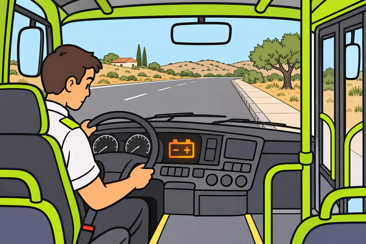
The battery supplies electricity, and the alternator recharges it while the engine runs.
| Part | Function |
|---|---|
| Battery | Stores chemical energy and supplies electricity |
| Alternator | Converts mechanical energy into electricity and recharges the battery |
| Regulator | Controls charging voltage |
Remember
- If the charging light stays on after starting, suspect a fault.
- Do not read this light as a measure of stored energy.
- Keep flames and sparks away: charging a lead-acid battery can release gases.
- In hybrid and electric buses, leave high-voltage work to qualified personnel.
- Do not assume high-voltage equipment is safe after disconnecting the auxiliary battery.
Exam trap: Wrong: disconnecting the auxiliary battery removes all voltage in hybrid and electric buses. Right: this does not prove the whole system is free of voltage.
Read the full explanation
- The battery stores chemical energy and supplies it as electrical energy for starting and for systems that need it. The alternator converts mechanical energy from the engine into electricity and recharges the battery; the regulator controls the charging voltage.
- The charging warning light may come on during the initial check and go out after the engine starts. If it stays on or comes on while driving, it may warn you of a fault in the alternator, regulator or electrical system; it does not directly measure the amount of energy stored in the battery.
- In a lead-acid battery, the electrolyte takes part in the charging and discharging reactions. Charging can release gases: you must keep flames and sparks away.
- In a hybrid or electric bus, the auxiliary battery and the traction battery have different functions. You must leave work on high-voltage equipment and cables to qualified personnel; disconnecting the auxiliary battery does not prove that the entire system is free of voltage.
11Diesel engine starting system
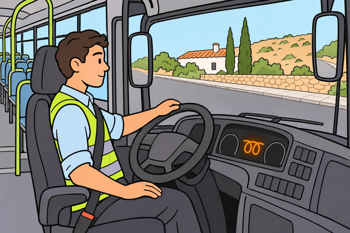
The starter motor uses battery power to turn the crankshaft.
| Diesel engine part | Function |
|---|---|
| Starter motor | Turns the crankshaft |
| Glow plugs | Supply heat for cold starting; do not produce an ignition spark |
Remember
- Remember: the starter pinion engages the flywheel ring gear, then disengages after starting.
- Identify the relay or solenoid: it connects the high-current circuit.
- Follow your model's preheating indication.
- Do not operate the starter for prolonged periods.
- Follow the manufacturer's limits for starting attempts and pauses.
- Release the control when the engine starts.
Exam trap: Wrong: a click without engine rotation proves the battery is faulty. Right: connections, the solenoid or the starter motor may also be faulty.
Read the full explanation
- The battery supplies current to the starter motor, which turns the crankshaft until combustion begins. Its pinion engages with the flywheel ring gear and disengages when starting is complete. [DGT, Manual VIII, starting system](https://sede.dgt.gob.es/.galleries/permisos-de-conducir/certificacion-aptitud-profesores-formacion-vial/2023/Manual-VIII-Mecanica-2023.pdf).
- When you operate the key or button, the relay or solenoid closes the high-current circuit; in a conventional assembly, it also moves the pinion into engagement with the ring gear. This prevents the full starter motor current from passing through the driver's control.
- Glow plugs provide heat to help a diesel engine start from cold. You must follow the model's preheating indication; they do not produce the ignition spark used in a petrol engine.
- If you hear a click without the engine turning over, there may be insufficient battery charge, faulty connections, or a fault in the solenoid or starter motor. The sound alone does not allow you to locate the fault.
- Do not operate the starter for prolonged periods: you can overheat it and discharge the battery. You must follow the manufacturer's instructions for starting attempts and pauses, and release the control when the engine starts; assistance from an external power source is covered in «Bus maintenance and checks».
12Switching off the engine and refuelling safety
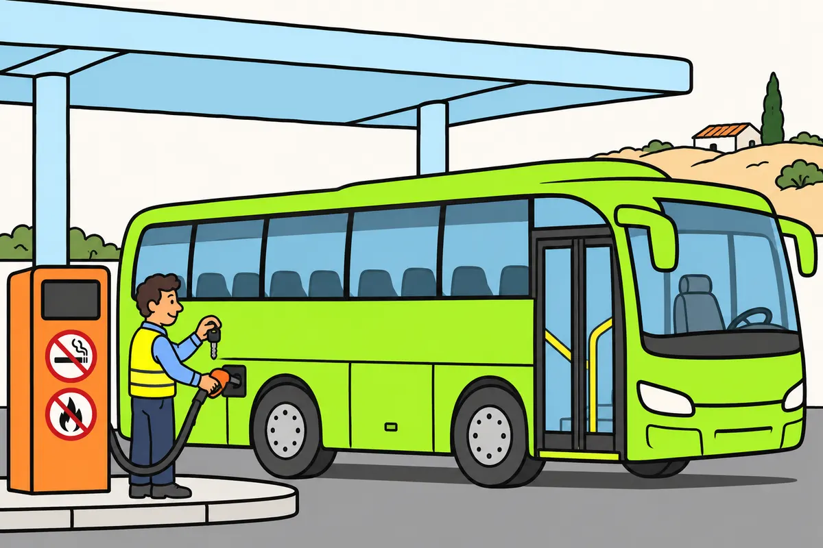
Switch off the engine when refuelling or when stationary in tunnels or enclosed places.
| Situation | What you do |
|---|---|
| Refuelling | Stop the engine. You must not receive fuel with lights, radio or mobile phone on. Without an attendant, switch them off yourself. |
| Stationary in a tunnel or enclosed place | Switch off the engine even if you remain at the wheel |
| Stop lasting more than two minutes in a tunnel or enclosed place | Keep the engine off until you can continue; keep position lights on |
Remember
- Stop the engine. You must not receive fuel with lights, radio or mobile on.
- Without an attendant, switch off the lights, radio and mobile phone yourself.
- At the filling station, do not smoke or light a fire.
- In tunnels or enclosed places, switch off even if you remain at the wheel.
- In tunnels or enclosed places, waits over two minutes mean keeping the engine off.
- In that case, keep your position lights on.
Exam trap: Wrong: in a tunnel, you can keep the engine running if you remain at the wheel. Right: switch it off whenever stationary.
Read the full explanation
- You must switch off the engine to refuel. You cannot be served fuel with the lights, radio or mobile phone switched on; if you refuel without an attendant, you must switch them off yourself. [RGC, art. 115.3 and 4](https://www.boe.es/buscar/act.php?id=BOE-A-2003-23514#a115).
- You must not smoke or light a fire at a service station; these are safety prohibitions for the premises. [RD 706/2017, ITC MI-IP 04, section 10.7](https://www.boe.es/buscar/act.php?id=BOE-A-2017-9188).
- You must always switch off the engine when the bus is stopped inside a tunnel or enclosed place, even if you remain at the wheel. If the wait lasts more than two minutes, you must keep the engine off until you can continue and keep the position lights on. [RGC, art. 115.1 and 2](https://www.boe.es/buscar/act.php?id=BOE-A-2003-23514#a115).
13Suspension and stability
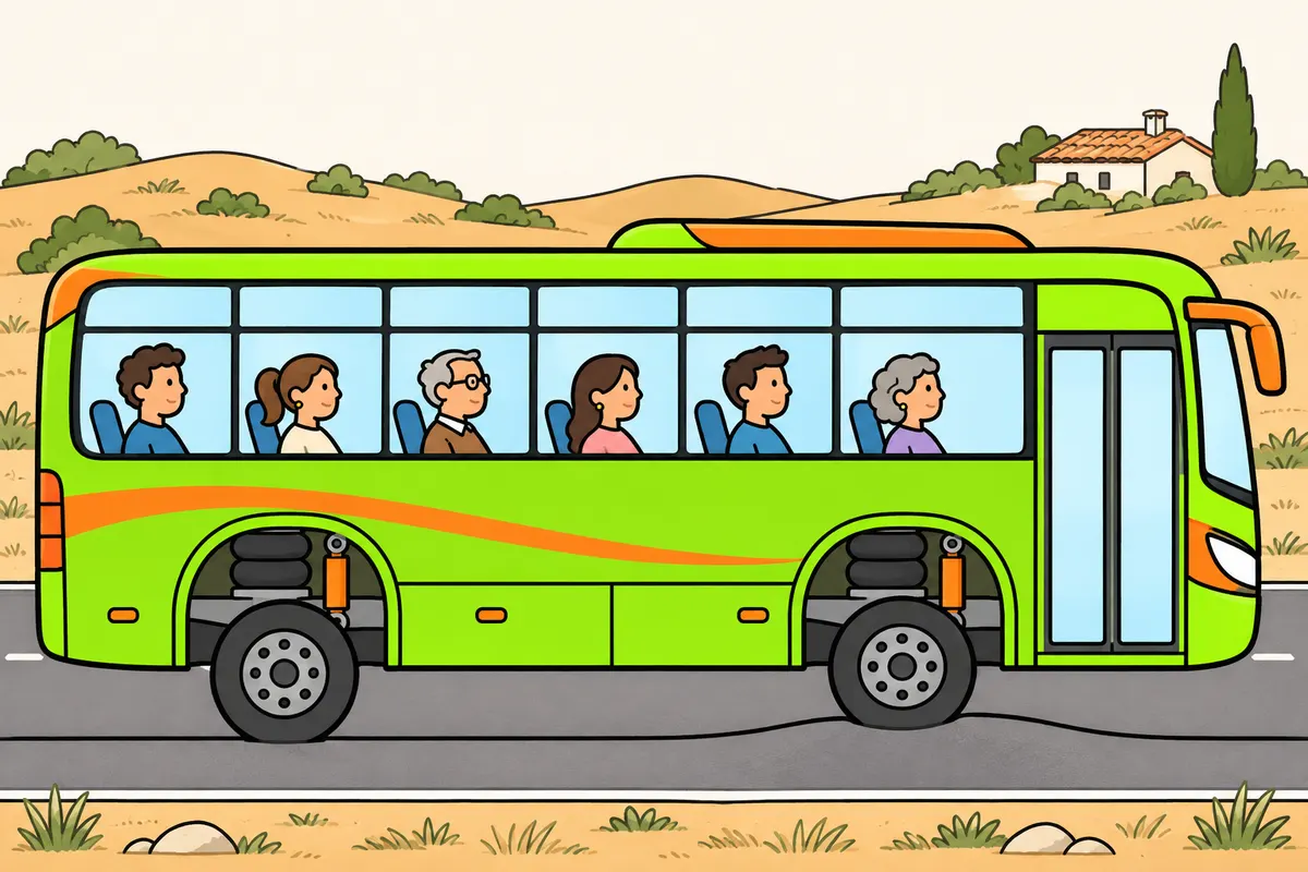
Suspension keeps wheels touching the road and reduces jolts.
| Part or function, where fitted | Purpose |
|---|---|
| Spring elements | Support the load and deform over uneven surfaces |
| Shock absorbers | Damp bouncing movements |
| Anti-roll bar | Limits body roll |
| Kneeling | Lowers the entrance height |
Remember
- Remember: suspension condition affects grip, steering, braking and comfort.
- With worn shock absorbers, expect possible bouncing and poorer road contact.
- With air suspension, identify the air bellows and height-control valves.
- After kneeling, restore the driving configuration according to the manual.
Exam trap: Wrong: shock absorbers only support weight. Right: they damp bouncing movements; spring elements support the load.
Read the full explanation
- The suspension connects the wheels and axles to the bodywork while allowing relative movement. It keeps the wheels in contact with the road surface and limits the jolts transmitted to the structure and passengers. Its condition affects grip, steering and braking, as well as comfort. [DGT, Manual VIII, topic 9](https://sede.dgt.gob.es/.galleries/permisos-de-conducir/certificacion-aptitud-profesores-formacion-vial/2023/Manual-VIII-Mecanica-2023.pdf).
- The spring elements support the load and deform in response to uneven surfaces; the shock absorbers damp their oscillations. A worn shock absorber can allow bouncing, body roll and loss of effective contact with the ground.
- On many buses, air suspension uses air bellows as spring elements and valves to regulate the height of the bodywork. The kneeling function lowers the boarding height; you must restore the driving configuration in accordance with the manual before moving off.
- The anti-roll bar limits body roll by linking the suspension movements on both sides of the axle. The air bellows, shock absorbers and mountings work together to control body movements.
14Exhaust and exhaust after-treatment
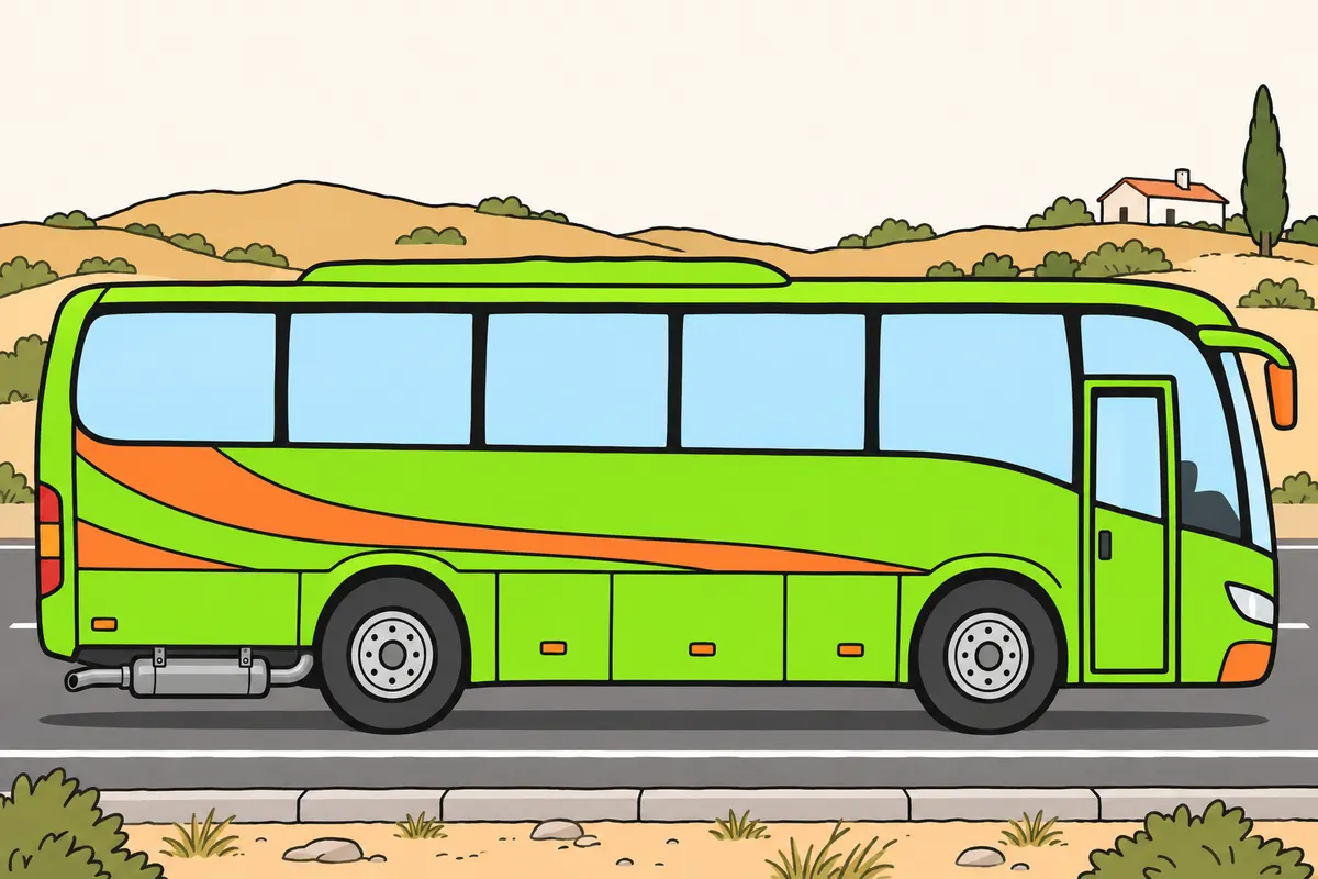
Distinguish the systems that reduce noise, soot and nitrogen oxides.
| System, where fitted | Function and care |
|---|---|
| Silencer | Reduces noise |
| Particulate filter | Traps soot; follow regeneration warnings in the manual |
| SCR catalytic reduction | Reduces nitrogen oxides; AdBlue has its own tank and must not mix with diesel |
| Exhaust treatment systems | Do not disable them or regenerate while stationary where heat could cause damage |
Remember
- Do not drive with an unsilenced exhaust or an incomplete, unsuitable or damaged silencer.
- With diesel engines, do not identify a specific fault from black smoke alone.
- Consider insufficient air or too much fuel for the available air as possible causes.
- When petrol or diesel burns, CO₂ is the main greenhouse gas in exhaust emissions.
- Methane and nitrous oxide may also be present in smaller quantities.
- Remember: a battery electric vehicle can generate emissions during its life cycle.
Exam trap: Wrong: you put AdBlue in the diesel tank. Right: use its separate tank; never mix it with diesel fuel.
Read the full explanation
- The silencer reduces exhaust noise. You must not drive with an unsilenced exhaust or with an incomplete, unsuitable or damaged silencer. [RGC, art. 7.2](https://www.boe.es/buscar/act.php?id=BOE-A-2003-23514#a7).
- In a diesel engine, black smoke can indicate incomplete combustion producing soot because there is too little air or too much fuel for the available air. Causes include a blocked air filter and incorrect fuel metering. The colour alone does not identify a specific fault.
- When petrol or diesel is burned, CO₂ is the main greenhouse gas in the exhaust emissions. Methane and nitrous oxide may be present in smaller quantities. A battery electric vehicle produces no exhaust gases while driving, although its life cycle may generate emissions.
- On buses with a particulate filter and SCR catalytic reduction, the filter traps soot and the SCR system reduces nitrogen oxides. AdBlue goes in its own dedicated tank and must not be mixed with diesel; follow its warnings and regeneration warnings in accordance with the manual. Do not disable these systems or carry out stationary regeneration where the heat from the exhaust could cause damage.
15Tyres: construction and reading their markings
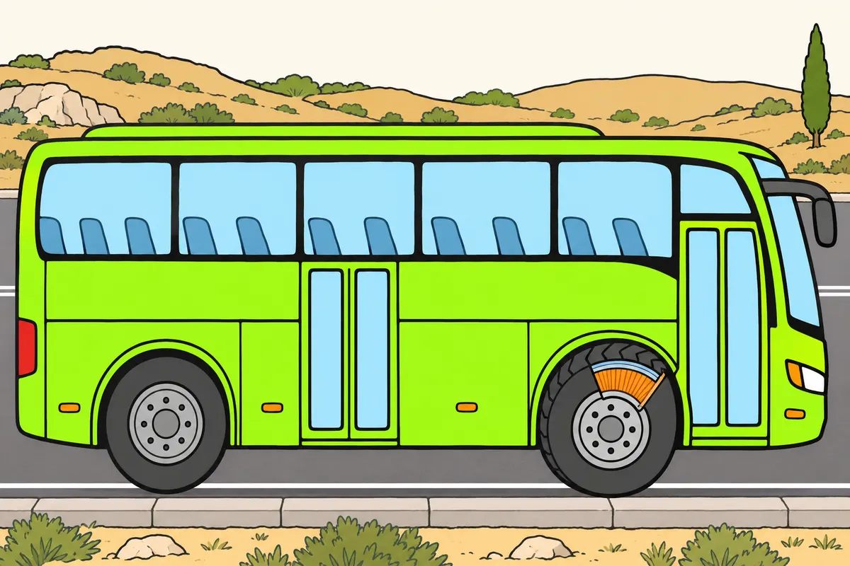
Learn what your tyre construction, sizes and symbols mean.
| Tyre construction or marking | Meaning |
|---|---|
| Cross-ply | Plies cross at alternating oblique angles |
| Radial: R | Cords run approximately perpendicular to the tread; a belt stabilises it |
| 315 | Nominal section width in millimetres |
| 80 | Section height as a percentage of width |
| 22.5 | Nominal rim diameter in inches |
| 156/150 | Load indices per tyre: single and twin fitment, respectively |
| L | Tyre speed category |
| TUBELESS | No inner tube |
| M+S | Snow tyre |
| 3PMSF | Mountain with three peaks and snowflake: approved for severe snow conditions |
Remember
- Identify the carcass: it supports the load of the inflated tyre.
- Recognise the beads: they secure the tyre to the rim.
- Find the sidewalls between the beads and the tread.
- Remember: the tread touches the road, protects the carcass and provides grip.
- With TUBELESS, you need an airtight tyre, rim and valve, with correctly seated beads.
- Observe your bus's speed limits even if the tyre allows higher speeds.
Exam trap: Wrong: L lets you drive the bus at 120 km/h. Right: it indicates tyre capability; observe your bus's speed limits.
Read the full explanation
- The carcass is the load-bearing structure that supports the load of the inflated tyre. The beads secure it to the rim; the sidewalls connect this area to the tread, which contacts the road surface, protects the carcass and provides grip. [UN Regulation 54, paragraphs 2.3 and 2.6 to 2.8](https://www.boe.es/buscar/doc.php?id=BOE-A-1987-17520).
- In cross-ply construction, the plies cross at alternating oblique angles to the centre line of the tread. In radial construction, the carcass cords run from bead to bead approximately perpendicular to that line, and a circumferential belt stabilises the tread. The letter R in the marking identifies radial construction. [UN Regulation 54, paragraphs 2.2 and 3.1.3](https://www.boe.es/buscar/doc.php?id=BOE-A-1987-17520).
- In the example 315/80 R 22.5, 315 is the nominal section width in millimetres; 80 is the section height as a percentage of that width; R means radial and 22.5 is the nominal rim diameter in inches. [UN Regulation 54, paragraphs 2.15, 2.17 and 3.1](https://www.boe.es/buscar/doc.php?id=DOUE-L-2008-81371).
- In 315/80 R 22.5 156/150 L, 156 is the load index per tyre in single fitment and 150 is the corresponding index in twin fitment: these represent 4,000 and 3,350 kg per tyre respectively under the specified conditions. L indicates a speed category of 120 km/h; this is a tyre capability and you must observe the speed limits that apply to the bus. [UN Regulation 54, paragraphs 2.27 and 2.28 and Annex IV](https://www.boe.es/buscar/doc.php?id=DOUE-L-2008-81371).
- TUBELESS identifies a tyre without an inner tube: airtightness depends on the tyre, rim and valve assembly, with the beads correctly seated. [UN Regulation 54, paragraph 3.1.6](https://www.boe.es/buscar/doc.php?id=BOE-A-1987-17520).
- M+S identifies a snow tyre; the 3PMSF pictogram, a three-peaked mountain with a snowflake, certifies compliance with type-approval requirements for severe snow conditions. You can study its use under winter restrictions in «Chains and winter equipment» in «Bus maintenance and checks». [RGV, Annex VII.5](https://www.boe.es/buscar/act.php?id=BOE-A-1999-1826#anvii).
From the battery to starting the engine
Follow the energy conversion that starts the diesel engine.
- The battery supplies electrical energy to the starting circuit.
- The command from the key or button activates the relay or solenoid.
- The pinion engages with the ring gear and the starter motor turns the crankshaft.
- Compression and injection allow combustion to begin; glow plugs help with cold starting.
- Once starting is complete, the pinion disengages and the alternator supplies the electrical system while the engine is running.
Air and fuel flow
The two circuits meet in the combustion chamber.
- Air passes through the filter.
- The turbocharger's compressor increases its pressure and the intercooler reduces its temperature.
- The intake carries air to the cylinders.
- The fuel circuit filters the diesel fuel and generates injection pressure.
- The injectors spray the fuel into the hot, compressed air.
From the engine to the driven wheels
The power flow through a conventional mechanical transmission.
- The clutch progressively connects the engine to the gearbox.
- The selected gear ratio adjusts torque and rotational speed.
- The propeller shaft transmits rotation to the final drive.
- The final drive reduces rotational speed and the differential allows the wheels to turn at different speeds on bends.
- The half-shafts transmit torque to the driven wheels.
Check what you know
Real questions from the bank on this topic. Pick an answer to see the explanation.
Finished this module?
Mark it as read and you will see your progress on the theory list.